>
YAMAHA
STRINGS
SS-30
RACK-MOUNTED WITH MIDI
MIDI STRINGS

Tuesday, December 03, 2019

YouTube - Quick demo of the Yamaha SS-30 String Synthesiser

This one's from JPMSynth, who appears to be an Ultraxox/Visage fan, here in the UK.

"Quick demo of the Yamaha SS-30 String Synthesiser, one of two stringers favoured by Ultravox in the 1980's due to its lush sound."


LFOVCF comments :
"Oh man! That's like warm honey poured in my ear!"

Thursday, March 07, 2019

A milestone

When I started this project I had a simple aim. I have expanded on that scope now, but the basic idea was to put the whole SS-30 into a rack-mount case, with MIDI. I have had MIDI working since last year but the front-panel was temporary. It was a proof-of-concept and not something I wanted to really play. Not ready for the studio.

As of last night, I have achieved what I set out to do. An SS-30 I can play in my studio from a MIDI enabled rack mount.


I had to replace almost all the faders. I suspect that the wobbly, ill-fitting, fader knobs just did something horrible to them.
Anyway! The panel was as good, if not better, than the original design. Although I hadn't added the additional features yet - pitch CV in, external Orchestra input, Orchestra feedback, individual voice outputs, and yes this isn't the final front-panel and no the wiring isn't perfect and so on and on and on (but now is not the time to dewll on what is left to do.) - but I had got the optimised control of voices with faders and dry/wet control of the Orchestra inputs.
And so, I decided to call a pause here, fit the front-panel and lid, bolt the panel into my rack and enjoy the SS-30M!


I should have some new fader caps tomorrow and I will work up some audio or videos soon to show off what I've got.

Good, eh!?

Tuesday, March 05, 2019

Noise Flaws

Bring The Noise!


This post will be me looking at why the SS-30M is so infernally noisy.

Since I brought it inside and started fiddling with output levels a bit I've become far more distracted by the noise-floor of the SS-30M. With a quiet 'studio' space with high-quality monitor speakers and headphones, the noise is far more obvious. Maybe not unignorably bad, but certainly not very good.
 
So far I have identified four types of noise


  1. Unidentified 'ticking'
  2. The Orchestra section's bucket brigade delays
  3. The 'swarm of bees' effect 
  4. General hiss

I'll start analysing each one and return to this post as and when I identify the root causes or fixes for each.


MIDI Interface 

The MIDI interface is the major new component in the system. On that basis alone it's a prime suspect for all sorts of issues. However, the first thing I did was disconnect the power to the interface and none of the problems were even slightly better.


Just a tick

This was a new (to me) and unexpected sound when I turned the gain up on the mixer and really listened. What is it? I don't know, but it sounds like a kind of click or tick sound every quarter of second or so. 

Possible sources - PSU switching, an oscillator (such as the orchestra LFO), other


PSU switching


If the PSU was a switch-mode type you might expect some switching noise (a ripple voltage), but that would be occurring at the switching frequency, which is much much higher. 
The reason I'm thinking of this is that when faulty they can exhibit similar ticking sound. It can't be that because the SS-30 supply is a linear supply.

But in a linear supply, there's no switching at all. It simply rectifying the 50Hz AC and filtering that. 

So, if it's coming from the PSU, I need a better explanation. 

LFO

 This occurred to me after switching off last night, but could this regular tick be coming from something the circuit which is already regular, like an LFO.

Orchestra LFO

The  Orchestra LFO is a pretty good candidate because a) it's operating in the right frequency range and b) there's a loose wire hanging off it at the moment. The wire is for the LED circuit, which I have yet to implement fully. You will recall that I had a breadboard set-up to demonstrate this. I remember when I got this design wrong, to begin with, drew too much current and caused ticking sound at the frequency of the LFO. 
So, I really need to check that wire and play with the Orchestra rate knob. If the ticking changes with the rate, then I have my culprit. If. 


Vibrato

The Vibrato LFO is a fixed frequency and is much higher than the Orchestra one. At around 6.4Hz, it does not fit what I'm hearing


That's all I have on the ticking, for now...


Orchestra Noise

 http://www.stefanv.com/electronics/oh-the-noise.html


That link is a nice article about reducing noise in a similar situation. The SS-30 has a high-cut filter on the output but is it enough? And if I change it, what then? A noise gate would be one way to go, but I can do that externally. 
The main issue that even when there is no signal going in there is noise coming out. Using the separate voice outputs should solve that to some extent, but it's not ideal. Preferably I'd be able to switch off the orchestra output altogether. I say preferably but it would lead to a set of control settings which produces no sound, which is something I'd prefer to avoid. The only way around that would be to have another balance control to replace the wet with a dry signal, but that's getting silly. A switch could be used instead which would bypass the orchestra and the orchestra depth controls. All more wiring, but possible.

The other thing about this noise is that it's masking the other noise. If I decide to leave it on, then there's not much point working on the others. 


 Swarm of Bees

 The so-called swarm of bees effect is the sound of all the notes buzzing away. As we know, the string synth design depends on keeping all the notes running continuously and raising their normally negative DC level towards 0V, so that they start to pass through diodes. If the negative DC voltage is too high you get all of the notes bleeding through the diodes even when no key is pressed. 

A possible source of the problem: supply voltage too high/positive, switching circuits not switching 'off' properly; sustain circuit not decaying fully, switching voltage from MIDI interface not 'off' enough leading to some bleed from the optoisolators, oscillator signal to large (peak-peak). 

So, lots to got at, there! This will be hard to isolate. As they are apparently all going at once, fixing one switching circuit will be hard to hear. However, with careful use of the scope, it should be possible to trace if they really are all bleeding through and if not all which ones. It will take some work though. 

Hiss-trionics

 General noise (hiss) is the bain of all analogue designs. Starting with the power supply and infecting every part of the design, noise is a fact or life. But some things are there to help and must be proven to still be working - i.e. de-coupling capacitance - and somethings can be upgraded - capacitance again, but also newer ICs. Not to mention the noise from electromagnetic interference. 
Good grounding, shielding, decoupling and so on will all help, but I'm not too hopeful. There's a risk of doing a lot of work to get a small benefit. I can't replace some components easily (or even at all) and working on each board is a major task, unless I desolder the wires and test each in isolation. Big jobs! Like, 'I need to quit the day-job' big. And finally, everything is now squashed into a small space. I need to be realistic and decide how bad it really is. 

I suspect that compared to the Orchestra noise the background noise-floor is quite small. 


Friday, March 01, 2019

2019 - Reawakening and wiring hell

And we're back.


Since last autumn, I've been busy with the usual life stuff, but also: building a pair of Eurorack clones of the Pearl Syncussion, engaging in a little friendly remix rivalry between friends and visiting China(!).  


Now all that is out of the way (well, the remixes will continue, I hope) I decided to put everything else to one side, for at least a week, and see if I could get the #3 temporary front-panel wired up and enjoy the use of an SS-30 with MIDI for a while. Maybe I could use it in my next remix challenge!

As it turned out, I burned through a lot of night-time hours this week battling with the wiring and even managed to blow two fuses and possibly a CMOS chip in the process. Grrr. It's a been difficult return to this project but after another epic session last night I seemed to have got it more or less under control. By which I mean that I know whats' going wrong and now have to fix it all! The good news is that apart from one real fault, the core of SS-30 is still working well and sounding great.

SS-30M panel wiring part 128,765


 I nightmare of wires

General issues with short circuits due to bad soldering and wiring management. 

    • This continues to be a big challenge. What is the solution? 
      • Ideally, all the wires would be terminated at a PCB and then all the controls would be on either the same PCB or another one connected via a ribbon cable, or several. 
      • Instead, every wire is going straight to the pin of the control where it's needed.
      • On top of that, most wires are shielded, and the shield is earthed and there's nowhere to 'tie off'' these shields on the panel
      • In some cases, the shield is not earthed so the shield has to be trimmed off, but there's still a risk of loose braids touching something and causing issues

Viola voice fader faulty? 

  •  I've disconnected most of these faders, for now, as they all seemed to be causing me problems of one kind of another.
  • Something definitely is up with this fader though.
  • I suspect it has taken a bad knock at some point 
  • Or, it was maybe that the too large fader caps are causing stress on it.
  • I will return to this one when everything else is sorted out. 

Lower Cello voices - disconnected wire.

  • The whole bottom octave of the cellos was missing.
  • This was fairly easy to find and was just the usual problem of a wire snapping off at the solder joint.

Wrong potentiometer used for the orchestra send. 

  • I had stupidly selected a log part, instead of linear.
  • This resulted in either all Orchestra or no sound for the Violin or no orchestra or no sound for the Cello. Or, something weird anyway.
  • I have had to use a pair of 50KB pots I had in stock in place of the 100KA's I'd bought.
  • I'm now concerned that too much sound is coming through to the Orchestra when it's supposed to be off and this design needs to be re-thought. 
  • Even using a 100KB instead of a 50KB part (I only had one suitable 100KB to hand) there was ~400mVpp getting through to the Orchestra circuit. 
  • Maybe I should use a dual concentric linear pot with ground on opposite ends so that I can get better isolation.
  • I think I have some of these ready to go in!

Lower G2 Viola voice not switching off when split

  • This is the worst one...
  • Even when I was getting no sound from the Cellos, for a variety of reasons (see above), I was always getting the bottom half of the second octave coming through the Violin signal path.
  • When I checked the switch gate, it was clear that the bus of notes (G2-8L, or the lower part of the 8' from the G2 board) was apparently not being switched off when it should be.
  • The switch gate is mostly composed of two quad CMOS analogue switches - TC4016P parts. 
  • On this particular switch, the G2-8L bus should be switched to the Viola's voice when the split is for Violin and switched off when the split is for Cello. 
  • However, it is never switched off. 
  • When Cello is selected, those notes are what you normally get normal and you obtain an even thicker sound. 
  • That might be considered an optional feature - Cello + Viola, instead of either/or.
  • However, I have no desire to redesign the switch gate!
  • I have ordered a replacement 4016 but tonight I will double check that the wire from G2 that brings that signal in, is not simply shorting to the wire taking it back out.
    • that would certainly account for the input matching the output!


In conclusion, I have still to get all the controls sorted out. I haven't even started on some of the additional features, such as Orchestra feedback, Orchestra external input, pitch CV and the Orchestra LFO LED. 


Update 1

Orchestra pot (like pit, but pot? Oh, why do I bother?)

Did I say dual-gang linear? Ha, of course, I was still not 'getting' what I needed here. What I actually needed was a dual-gang log taper pot. Thus, as the dry signal fades out, the wet signal fades in. Luckily I had exactly two such pots of the right size. Phew. That's working perfectly for both now. 

Coming in hot

I added a 100K to ground on the Violin Orchestra input and a 10K for the Cello Brilliance to bring the level down a bit as it seemed to be distorting a bit when a lot of keys were played. I'm not entirely sure why the violin one was needed, but the Cello volume control (now removed, of course) had some resistance to ground and it was coming through very 'hot' without it. I might tweak these again later. 

Fade to nay

I made a start on reconnecting the voice faders, but I still have problems with some. The Cello 2 fader was as far as I got, but it wasn't working right. 


Update 2 

Viola Split Fixed


Last night I fixed the Viola split problem by fitting a new 4016 analogue switch. As soon as I'd got the LF board free I noticed that I have already replaced its companion. A quick search of the blog reminded me of this post: Viola Woes

Attack issue

After checking the Viola was switching right I spotted another issue. The same notes that were coming through as Viola still sounded different. Not to worry though, this wasn't the Viola but something else. In fact, once I'd tried different splits and attack settings I realised that the whole bottom octave had no attack setting. Attack is short when switched to ground but this one wasn't. After a bit of messing around with the split switch, I suddenly spotted that there was loose brown wire next to the K1 switch board. Of course! although there was a brown wire attached to the correct pin on the K1 board, it was only the one coming across from the other side of that same board! The wire to the split switch was loose. Soon fixed, and everything was back to normal. 

In the past, I've been a bit unsure about the attack. How much is it really working and what is the point of it, really?
 I wonder now though. The more I play the SS-30M the more obvious it seems and the more I appreciate what Billy Currie was saying about the character of it better now. This all comes from being able to really just play it.


Monday, October 08, 2018

Yamaha CP-1 - Sympho effect?

Something strange I stumbled across whilst Googling.

In their 2010 review of the Yamaha CP-1 stage piano,  Sound On Sound listed the onboard effects. One of them was described thus:

"Sympho (a multi‑stage chorus from an unspecified Yamaha string machine)"
 My underlining.

Unspecified? There is only one Yamaha Strings Machine, the SS-30.  I wonder where the reviewer got this info from?

There is no strings synth emulation among the presets on the CP-1. Yamaha must have just decided to include this chorus because it sounds so great.

Digging deepr into the CP-1 manual I found this

  • Chorus - The Chorus effect applies a standard chorus.
  • D Chorus - D Chorus produces a chorus effect that is more natural sounding, softer, and wider.
  • 816Cho(816Chorus) - The 816Chorus effect reproduces the thick, detuned chorus of the TX816 — famous for combining eight DX7s in a single rack unit.
  • Sympho (Symphonic) -Symphonic uses multi-stage modulation to produce a wider-sounding chorus.
Obvioulsy it's stereo as wider means between left and right speakers. So, it can't be exactly the same as the SS-30. Hmm...


Monday, September 24, 2018

Temporary Front Panel (Again)

Last time I was talking about trying a laser print transfer method.

I started with a spare piece of aluminium panel and a print of my design (which I forgot to create as a mirror image first...).


After varnishing the metal and sticking the paper face down I waited for it to dry. Next it was matter of wetting the paper and removing it. Gently!


Not gently enough in my case.

Image mirrored


Still, I had done enough to prove that I could layout a panel exactly as I needed it with labels etc. as well as marks for all the cuts in just the right places. This was particularly important for the slide potentiometers whose tiny 2mm mounting holes have to be located 'just so'.

I was confident I could do better next time and after a few more tweaks to the design I was ready to go.

Verorack panel
Panel fitted to case


Panel with print aligned ready for varnish

Print folded over the varnished panel


Gently does it...

No matter how careful I though I was being, I still ended up removing too much ink. Part of the problem is that the Vero panel is brushed, textured finish, whereas the other piece was smooth.

Anyway, it was good enough and I got drilling!


One issue I noticed, soon after fitting the knobs, was that the slider caps do not sit quite right. There's a bit of wobble. I will have to deal with that at some point...


Once I was reasonably happy I sprayed a layer of matt varnish and refitted the components.


Note that for the Pitch control and the KYB. SPLIT controls I cut and reused the original SS-30 sub-panel plates to mount these controls at just the right depth.

And so, at long last I've brought the SS-30 indoors. The plan now is to wire up the panel in the comfort of my studio space. I've made some room in my rack and I'm all set!

Space for the SS-30M


Sunday, September 23, 2018

Controls and Connectors

Some notes on the controls and connectors

Rotary Potentiometers

With the exception of the pitch/detune I've decided to use all new rotary potentiometers. For the relatively small price, the peace of mind is worth it.
I need T18 6mm shafts for the knobs to fit onto and there are 11 in total. 1x 50KB for the vibrato delay; 4x  10KB for vibrato depth, sustains and Orchestra speed; and x6 100KA for the rest.

I've decided to go with the vertical mount 9mm Alpha pots from Thonk.


https://www.thonk.co.uk/wp-content/uploads/2017/12/Alpha-9mm-Vertical-T18-RD901F-40-15K-B50K-0057.pdf

9mm-Vertical-T18-RD901F-40

9mm - Approx 9mm body
Vertical - PCB mounted vertically.
T18 - 6mm 18 tooth, split, splined shaft.
RD901F -  Model number
40

Pins - 1mm hole, 2.5mm spacing.
Hole - 7.1mm

After getting these in my hands I realised that the shafts are far too short to fit to a sub-panel and through the front-panel. I fitted one to my old temporary front-panel.


It actually fits really well. The skirt on the Yamaha knobs covers the nut and washer and is just far enough away from the panel to work. This means I don't need a sub-panel for these rotary controls at all.
However, if I want to use any other knobs, such at this one, which does not have any skirt to hide the washer
 ...then I will need a different pot with a longer shaft.

And the pitch-detune dual-concentric control still need a sub-panel,as I plan to reuse the original part.


Slide Potentiometers


The slide potentiometer is from Bourns.

Bourns 60mm slide potentiometer


https://www.bourns.com/pdfs/PTA.pdf

PTA4543-2015DPA103

PTA
45 - stroke length mm (45 = body length 60mm)
4 - no dust cover - 5 = dust cover
3 - single gang
-
2  - Pins facing down (PCB)
0 - No detent
15  - Lever length
DP  - Lever style
A - Audio Taper
103- 10KOhm


Mounting is difficult. I would like to screw them in place, but the screw has to go into the face of the slider. This means that the height of the lever is critical.
Assuming the knob needs 10mm of the 15mm available and the front panel is 3mm, there is almost no space left for a sub-panel and screw. The sub-panel would have to be 1.5mm (thinnest available from Schaeffer) and the screw would be counter sunk. This sub-panel would then be bolted tight to the front-panel although, in theory, it could be bolted to another sub-panel behind and pushed into the back of the front-panel.

I have ordered some small 2M screws and think this might be the way to do it.


MIDI DIN Connectors

 I'm not a fan of most cheap DIN connectors which have two fixing holes, either side of the socket. I have a bunch of these in a drawer but I wanted something nicer.
Instead, I looked for a part that fits in from the front with a single nut fixing from behind, and found one at Farnell.
http://uk.farnell.com/deltron-components/650-0500/socket-din-screened-180deg-5pole/dp/1193837
Oh, but it was pricey. Eventually I found that CPC, who are part of Farnell had then from half the price. Go figure.


1/4" Jack Sockets

These are Neutrik, so ought to be pretty good.


These were also cheaper at CPC, but I'd already ordered from Farnell.
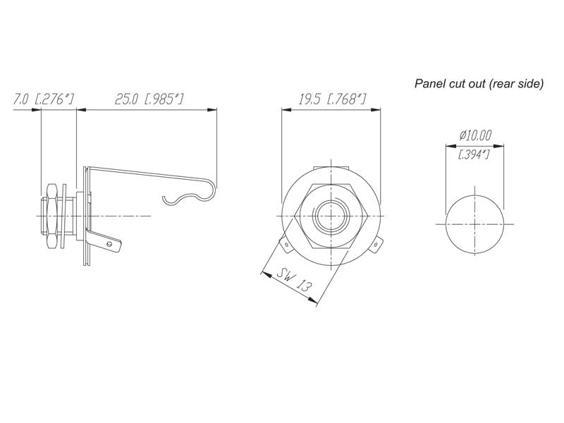
http://cpc.farnell.com/neutrik/nys229/1-4-jack-panel-socket-mono/dp/AV09109
 
Dimensions
https://www.axecaster.co.uk/images/NYS229_specs.jpg

Cliffcon Miniature ZC Series

I've covered these before in the power supply posts 
http://www.cliffuk.co.uk/products/cliffcon/zcseries.pdf

PowerCon

I've covered these before in the power supply posts
Drawing+NAC3MPA-1-WOT.pdf


Tuesday, August 21, 2018

2018 - Wrapping up?

2018 Summer-y 

 Once again the end of summer has come around far too soon. I can't complain about the summer we've had this year. Three months of solid warm weather meant I was able to make huge strides forward on SS-30M. It's never enough for me though. I want to finish. On the other hand, I don't want to rush and make a bad job of it.

Technically, summer's not over yet but I know there's limited time remaining and I won't be spending as much of it on eth SS-30M as I would ideally like. I also have other projects waiting for attention. There's the Hex inverter 808 Toms clone Eurorack module that was dropped back in April. I have Eurorack kit clone of the Pearl Syncussion coming soon. And I also started an 808 cowbell module of my own design. I might even record some music. I recently acquired a Yamaha Reface CS which I want to explore, not to mention a whole load of other gear that has sat idle for far too long. 

Temporary Front-panel #2

Does that mean the SS-30M will sit in the garage for another 8 months or more until I can get around to carrying it on? Maybe not.  I could wire up a temporary front-panel and use the SS30 in the meantime!

Ah, but what front panel? I have the old wooden mock-up one I have laser cut in 2015, but that doesn't match the latest design. I also have a design which I could get made by Schaeffer, but it will need a lot of work and that's better done in the winter. I could get another cheaper laser cut of course. There's another option though - make my own. And now I have a pillar drill that would be a lot easier...


Oh, yes, I got a pillar drill.


I have two stipulations for myself :
1. It must have labels for the controls.
2. Don't get bogged down with sub-panels.

 Fair enough, so wood or metal? I think metal this time. If I actually want to rack mount it, that's the best option.

Vero Panel


I had been fretting about the dimensions of the front panel's fixings because I didn't have a datasheet for the case and wasn't sure if I could get one. It turns out that the APW case I bought back in 2005 is still available from Verotech. They must have bought out APW or something. Anyway, the data-sheet doesn't actually tell you the dimensions for the fixing holes. There are only dimensions specified for the handles designed to fit into the holes. Ugh. I will have to write to them and get that info. 
The other thing I realised was that you can still buy all the accessories for the case. For example, the tray that fits into the base. I might come back to that! Farnell sells the front-panels and that's what I need. It would fit perfectly, so that is one less problem. In the end, this is a no-brainer, as anything else would cost the same (or more) to buy and have cut.
So, I just went ahead and bought one.

The only problem is that I really would like to have slots for the sliders. I'm not sure how to do that cut yet.  It will probably be a bit of a bodge, (drill then saw) unless I can think of a way to pretty them up.

Varnishing Act

With the panel bought, now I have to decide on labels. Actually I have two problems with marking the panel. The labels, of course, but also marking it up for drilling. That got me thinking. 
Ideally, I would print onto the panel and use the print for labels and to mark out where the holes should go. Wouldn't that be great?
Of course, I can't print onto the panel, but there is a way. Sort of.
I'd looked before at the Lazertran decal process for inkjet printers and also toner transfer methods for making PCBs. Searching again threw up a different method. In fact several methods for transferring from a standard laser print to paper to just about anything flat.

I was most impressed by this video.


I've bought some varnish and I'm going to try this out on a spare aluminium panel I have.

If it works, I can create a decent print which will provide guides for drilling and excellent labels in the exact font and design I intend to use for the real one later. 


Tuesday, August 14, 2018

Japanese Videos

Distincly odd (or is that just because it's Japanese?) video of a young woman playing an SS-30 which is perched on top of a motorbike.


"You did not expect to play strings from Masashi Sada's songs.
Do you know this musical instrument?
Only the sound of strings comes out!
It is the forerunner of the recently released Refs series!
Sorina [presumaly Solina] who played before was also good, but this one is also not losing!
Yamaha will do it too! !
This valuable musical instruments now is 130,000 yen, but I will price it if you say it with anything!
Instead, please buy a dozen of beers! !
Older brother, this bike ... I saturated. Why buy a new one?
"


Here's another one which is only 15 seconds long

"Inventory, so many repaired items so I received ...
Rhodes Mk 1 Mk 2 Together 4, Korg organ BX - 3, Yamaha E 30, Oberheim 's synth, Clavinet D 6, Hammond B 3, Hammond T type ...
This SS 30 is an inventory"

Tuesday, August 07, 2018

Brought to book

For me, googling the SS-30 is can sometimes feel a bit like googling yourself. In fact, sometimes it comes to the same thing, as I found with the Amazona.de article! But what I mean is it can feel a bit desperate. A bit needy. A bit sad. But it often pays off.

Today I felt the need to google 'Yamaha String Synthesiser' and this post on Matrixsynth from 2014 popped up. It's mostly unremarkable. Another eBay auction, which is no longer available to view.

The nice thing about Matrixsynth is that it stores the photos and any interesting text.


 In this case, the text is rather interesting...

If you want classic analog strings, this is what the Yamaha SS-30 excels at. All this machine does is make superlative string sounds - there's no Brass or Organ settings here. If you won't take my word for it, just look at the following Youtube link of Ultravox's 1982 Monument tour where two Yamaha SS-30s were used by Billy Currie and Midge Ure. [video here] This synth is all over the first 3 post-Foxx albums - Vienna , Rage in Eden and Quartet. Opening chords on The Voice , Reap the Wild Wind, Vienna,Hymn Also used a lot by John Foxx on Metamatic

This synth totally blows away the Moog Opus 3 , Korg Delta , Roland RS-09 , RS-202 and it's only competitor is the Roland RS-505 Many people looking at this auction will also have Peter Forrest's excellent A to Z of analog synths book and I would urge you to read his review of the SS-30:-
"played in a realistic manner,sounds very good. Even without the Orchestra modulation on, it sounds very good. And through a classy hall room reverb setting it sounds very, very good. It just goes to show that it's better to do one thing well,than three things to a so-so standard" 
I think this was a little dig at the Moog Opus and Korg Delta and some of Yamaha's own SK range. The real beauty of this machine is the phasey string sounds which come from Detuning the oscillators and swithching on the ensemble mode. The Decay is fully variable and the whole thing is built like a tank and weighs a ton..

A-Z Analogue of Synthesizers


As well as the general enthusiasm for the SS-30, Ultravox referencing and trashing of the alternatives, what's nice is that there is a quote from A-Z Analogue Synthesizers, a book (well, two books) I've always meant to track down. It's not clear if that is the whole entry or just an excerpt though. 

Let's analyse the statements Forrest makes. 

"played in a realistic manner, sounds very good."

This reminds me of what Billy Currie was saying in the GE-Force media interview. As a string player, he was impressed by the realism possible.

"Even without the Orchestra modulation on, it sounds very good"

I guess that means in relation to other stringers which might be very dull without the chorus effects.

"And through a classy hall room reverb setting it sounds very, very good"

The first thing I need to do when the SS-30M is finished is to get a classy hall reverb!

"It just goes to show that it's better to do one thing well, than three things to a so-so standard"

Well, of course. Having got the SS-30 by accident and decided to create the SS-30M because of it's poor mechanics it was not necessarily the case that I chose well in starting this project. But as time's gone on I can say that I've become more convinced that this is a worthwhile effort.

 Keyfax


Whilst (unsuccessfully) searching for copies of A-Z (N-Z) I stumbled across another book about synthesizers, Keyfax. There were five editions and an omnibus.  I found a list of synths covered in part 2 but despite including all the SK and CS Yamaha's the SS-30 seems to have been missed out.  I need to keep digging on this one but secondhand prices are not cheap...


Foxx?


One last thought. The statement that John Foxx used the SS-30 on is Metamatic album is not something I can corroborate. I might have to have another listen though.


Monday, August 06, 2018

Counter Attack! (Part 1)


Back in this Attack Formation post, I looked at how the attack setting could be made both longer and variable. I then dismissed the idea on the basis that changing 98 resistors was time consuming and risky.

But now, I'm thinking again. Really thinking. Hard.

This post is part 1. Once I've got the SS-30M powered up again I will check some things and come back for part 2.  Meanwhile this post is all worked out on paper and checked with a circuit simulator (iCircuit).

The attack control is a switch. You may recall that I bought and destroyed an entire organ to get hold of the right sort of switches for the front-panel design. I have used more controls from the donor organ than the switches in my design, but now I'm starting to wonder if I might go back to the idea of a variable attack control.

This is the basic idea - add a variable resistor where currently there's only a switch.

Doctored schematic of attack circuit
If I do indeed decide to go ahead with a variable control for attack this will have an impact on my front-panel design ideas. It's not something I can easily change later, so now is the time.

What follows is a fairly in depth analysis on the original design and the possibilities of changing resistors to achieve a better attack envelope.

Original Design Analysis

Let's start with a more thorough analysis of the original design.
Here's the datasheet for the transistor: http://rtellason.com/transdata/2sc458.pdf

The first thing to say is that the transistor is being used as a switch. Which is to say it's either in cut-off mode, where no current flows from collector to emitter, or near saturation mode (see below) where collector to emitter is a short circuit. It is in saturation mode is also used even when the collector is open-circuit. In this case, the current from base to emitter is what is significant.

Voltage 

Collector Voltage

 The collector is switched between open-circuit and ground by the Attack switch(es). Open-circuit means slow and grounded means fast attack.

Key Up

When the key is open the transistor is in cutoff mode. For the switching in general it doesn't matter what the collector voltage is at this point, so long as it is higher than Vb, but as it's open-circuit Vc will be the same as Vb, -7V. That's true in isolation, but below I look at the particular case for the collectors of all the attack circuits.

Key Down - Collector grounded

Clearly, when the collector is tied to ground the voltage (Vc) is tied to 0V and cannot be lower or higher. In saturation mode Vc must be lower than Vb and as Vb cannot be higher than 0V the transistor is actually in active  mode, where Vc > Vb > Ve. Therefore, thanks both to the presence of Rb and Vc being 0V, Vb is a small, negative voltage. I measure -0.7mV in simulation. This means the transistor is still close to saturation as Vc and Vb are almost the same and we can assume that there is no significant impact on collector-emitter current.

Key down - Collector open circuit.

When the key is down but the collector is open circuit there is a voltage on the collector. That is because as the transistor is in saturation mode and there is a short circuit between collector and emitter. Hence Vc is equivalent to Ve  and also less than Vb. I measured 540mV in simulation with a generic NPN BJT.

Collective Collectors 

The previous comments haven't referred directly to that that fact that the collectors of the attack control transistors of all the keys are connected together*. It's obvious, of course, that there is one* attack switch and 49 keys so they must be all on the same node.

When the attack switch is grounded there is no difference in the analysis. Ground is a node already. 

When the attack switch is open-circuit, all the keys are 'up' and all the transistors' Vb are -7V and all the collectors' Vb are also -7V.

But what happens when a single key is pressed?

As I noted above, for a single transistor, when the key is pressed and the attack setting is open-circuit Vc = Ve = 540mV, in simulation. If I copy the circuit and link the collectors together the common Vc is also 540mV. No surprise there! Even when only one key is pressed, all the collectors switch to the same -540mV of the one key that's been pressed because there is effectively zero resistance between them, compared to the potential brought about across the base-collector diode when the transistor is off.
With slight variances between resistors and transistors all the collectors' voltages (Vc1, Vc2... Vc49) will average out the more keys that are pressed.

Note that this means that if one transistor or resistor is wrong or faulty, the whole average for Vc will be thrown off, although not by as much as you might think. You might get one key bleeding though which is then silenced when you play another key though. One for the fault finders there!

In summary, all circuits being equal, the collector voltage doesn't matter very much in the SS-30 design. This will become important later on though, when the open-circuit attack setting instead becomes a resistance to ground.


* for the purposes of this analysis I'm ignoring the keyboard split and assuming all keys are controlled by the Violin attack switch.

 Input voltage - Key open


Base
When the key switch is open-circuit the input to Rb is held at -7V through a 3K3 resistor and a diode* in series with the -7V rail. As we’ll see, there’s no voltage drop across the base emitter junction and Vbe is 0V. Thus there’s virtually no drop across Rb and the potential difference between the -7V rail and the base is approximately 0V.

*I'm not totally sure yet why the diode is needed, but it's something to do with the emitter voltage on the other transistor, used to control Sustain time.

 Emitter
The emitter is also held at -7V. This potential comes through the two resistors, which I will call R Collector (Rc) and R Discharge (Rd), which is connected to the -7V rail.

In a more familiar circuit, it's as if the emitter is ground and the base is also switched to ground. You have to get used the 'ground' in this circuit being -7V instead of 0V.

Output Voltage - Key open

The output voltage is created by the divider between Re and Rd. In this state the potential is the same -7V throughout Re and Rd because the transistor base is also -7V. There is no voltage drop across the divider so there's no drop within it either.

The Service Manual quotes the output voltage as -6.5V +/-0.5V, which gives plenty of room for variance in the supply rail.*

*I'm not totally happy with that explanation, by the way. Maybe it varies with load.

Input voltage - Key closed

Base
The key being pressed grounds the node to 0V. Now the input to Rb is 0V and the base is at a higher potential than the emitter. This means the inherent voltage drop across the base-emitter diode, Vbe, comes into play. There is now a voltage divider made up of Rb, Vbe diode drop, Re and Rd. The base voltage is therefore a function of this divider and can be calculated thus.

-7V - Vbe = -6.3V 

Vb = -6.3V x (Rb)/(Rb + Re + Rd)
Vb = -7.45mV

The transistor is switched ‘on’ by this drop across base-emitter. Relative to Vc when it’s 0V, Vb is almost as high and the transistor is effectively in saturated mode. When Vc is open-circuit there is no collector current, so it’s effectively just a diode.

Emitter
The emitter voltage, Ve, must be Vbe lower than Vb which places it at -7.45mv - 0.6V = -607.45mV

Output Voltage - key closed

 The voltage divider Re Rd is now between Ve -0.607V and -7V. The voltage drop is thus 6.393V and the divider outputs a theoretical 0.014V.

That is the steady state voltage of this node anyway. The output voltage will rise to this near 0V level as the capacitor charges.

Current

There is only a small current once the capacitor is charged and actually the interesting thing here is the charging time, not the specific current.
Charging time (which I will call Tc) is a product of the series resistance and capacitance, which give the value of  tau - the time constant. The full charge time is effectively infinite, so to make this easier I've chosen a fully charged time of 5 x tau. Hence Tc  = 5RC.
5tau is the point at which 99.3% charging is achieved, and the voltage at Tc is therefore 0.993 x Vsteadystate. That's important!

Slow charge

First, let's look at the current when the collector is open circuit. This is the 'slow' setting and the collector current (Ic) is 0A.
In this state, the only current charging the capacitor comes via the base-emitter junction's current (Ibe). The base-emitter current Ibe is set by the 12K Rb and the 2K2 Re. In our case that is 14.4KOhm total.
Thus Tc = 5 x 14200 x 0.0000068 = 490ms. Right...?

In fact, this calculation is wrong because it ignores Rd. As we saw above, Re and Rd are a voltage divider, but how does that effect the charging time? The total R for our RC circuit is Rb+Re and Rd in parallel (and lets call Rb+Re 'Rbe').

The calculation for the parallel resistance is (Rbe x Rd)/(Rbe+Rd)
14,400,000/1,014,400 = 14,195.6KOhm
Which is only slightly less than Rbe, but if we start changing these values later it's worth getting this sort of thing correct from the beginning.
So:
tau = CR= 0.0000068 x 14,195.6  = 96.56ms
Tc  = 5tau = 483ms.

Is that right? I have simulated this circuit, and it is right! Not exactly, but very close. In fact, it is exactly right if you ignore the transistor and simulate it with only the resistors and capacitors.

Simplified RC circuit


In this simplified circuit the steady state voltage is 99.369mV (there's no Vbe to account for). Thus the total voltage charged is 6.90063V.
We're looking for 99.3% of that at Tc, which is 6.85V.
-7+6.85 = -148mV.
Which is almost exactly what the trace from my simulation shows at t=483ms (this application doesn't allow precise measurement, so the marker is the closest I could get.


With the transistor in the circuit, Tc is something like 531ms in the simulation.

Working that backwards...

531ms/5 =  106.2 ms = tau

R = 106.2ms/6.8uF = 15.617KOhm.

So, the base-emitter junction is adding around 1.2K of resistance to the circuit. I might need to come back to that, but for all intents it is a minor issue. As I will be increasing this overall resistance to achieve longer attack times this is trivial.

Using the sum of  the resistances Rb, Re and Rd and the total voltage drop of -7V the current through through this circuit should be:

I = V/R = -7/1,015,200 = -6.9 uA

Which is around what I get in simulation (6.4uA)  allowing for the approximate 1K of the base-emitter junction.

 Fast Charge

In this state the collector is grounded, there is no impedance at all there (no Rc) and Ic is effectively unlimited. Now the current Ice is contributing to the capacitor charging, so there is more current than is provided by the base-emitter alone. This leads to a faster charge and sharper attack.

The steady state current will be approximately, the same as with the collector open-circuit because only 12K will be removed from the calculation. It's now calculated as 6.976uA or 6.5 uA in simulation.

For the RC calculation though, removing the 12K has a more profound effect because large value for Rd (1M) is largely irrelevant.


R = RcRd/Rc+Rd = 2.195KOhm

tau = 2.195e3 x 6.8e-6 = 14.9ms.

Tc = 5tau = 74.6ms

Again this is the idealised model. With the transistor in simulation I got around 107ms for Tc (tau = 21.4ms).

Fast charge with transistor - Vd = 510mV


Which, calculating backwards, comes to a resistance of 3.147KOhm. So, again, about 1K of additional resistance due to the transistor, which is now more significant.

Original Design - Conclusions

Specification 

We only care about two parameters in the attack circuit. The output voltage and the time taken to reach it.

If we take 99.3% of the output voltage as being 'fully' charged and use it as our definition of when of this attack envelope time has elapsed then the two settings offered by the original SS-30 design are

  • Normal (fast) - 107ms
  • Slow - 531ms

And note also that the output voltage varies slightly (93mV) between normal and slow settings.

  • Normal -465mV
  • Slow -558mV
The output voltage is a function of Vbe and the voltage divider between Rb+Re and Rd.

Emitter Resistor

Increasing Re will result in lower (more negative) output voltages. It will also increase the ‘fast’ attack time. Neither which are wanted.

Lowering Rc will only lower the output voltage slightly, as Rd will still account for most of the voltage difference. It will also decrease the attack time (At), most noticeably for the fast attack. That could be worth doing!

Re↑ = At↑ & Vo↓

Re↓ = At↓ 

Base Resistor

Increasing the base resistor will increase the charging time for slow attack but would not significantly effect the fast attack.

It will significantly affect the output voltage when increased though, because the voltage divider created by Rb+Re and Rd sets Vo. As Rb approaches Rd Vo will decrease.

The collector current depends on Ib to a small degree but if  Vb is kept at near 0V there is little overall impact to the the Ice current unless Rb is extremely high.

There is no benefit to decreasing Rb.

Rb↑ = At↑ &  Vo↓

Discharge Resistor

Changing Rd will affect the Sustain time. The 1MOhm discharge resistor is high enough that it mostly cancels out when calculating the R value for the CR charging time, due to the product/sum calculation for parallel resistance.
i.e. R is always approximately Rb+Re.
If that ratio changes, then the effect will not be a linear relationship, again due to the product/sum calculation.

Collector

The collector has no Rc resistor and is either short to ground or open-circuit. Shorting the collector to ground kills any Vc voltage created across Vce, but when it is open-circuit there is a voltage potential there, which is shared across all the attack circuits.

Conclusion

Increase Rb to increase attack time and the output voltage will drop. A solution is needed which can maintain the voltage but still decrease the current to the capacitor. Care must be taken with Vc, which is common.


Improved Design? 

The desired improvements are two-fold

  1. Improved range of the attack times (faster and slower)
  2. Variable control of the range

Variable Control

Let’s start by replacing the Attack switch with a variable resistor and look at the state when the key is down and the transistor is on.

Voltage

When Rc is zero:
  • No difference to orginal design
  • Vc = Ve
  • The fast attack is just the same. 

When the resistance Rc is non-zero:
  • Vc is no longer equivalent to Ve as is divided between Rc and Vce.
  • Rc and Rb are now in parallel.

But:
  • Rc is still in series with Re.
  • Rb in still series with Re

Vo is thus now influenced by Rc as well as Rb and Re.

Let's call the parallel Rc and Rb resistance, Rcb.

Rcb  = (Rc*Rb)/(Rc+Rb)


Assuming Rb is still fixed at 12K what effect does Rc have on the output voltage? In summary very little. If it's very large it's effect is nullified by the moderately sized Rb. If it's very small it still has no real impact on Vo because Rd is still very large in comparison.

This means that whilst Rb is unchanged in relation to Rd, Rc can be any value. As we will see below though, when Rb is larger things get more interesting

Current

As already noted, adding a variable Rc control does nothing to effect the fast charge time, which is still a short circuit from ground. 

Also noted above, we can set the value of Rc to any value we like if Rb is the same because the output voltage is largely unaffected, due to the large value of Rd and the parallel resistance with Rb.

The value of Rc should then be high enough to mean most of the current for charging the capacitor is coming from Rb, as in the original design.

Again, assuming Rb is still 12K, what value would we use to make the attack time variable, but within the same limits? Recall that the charging time is given by R*C and R is the parallel resistance was Rbe and Rd. It's now the parallel resistance of Rc and Rb + Re in parallel with Rd. To achieve the same overall value for R, and thus the same attack time, Rc must be as high as possible. The higher it is, the closer Rc and Rb in parallel will be to just Rb.

That analysis is just for a single transistor though. When there are 49 transistors all taking current from Rc is that still valid? Err, Yes! I simulated up to 12 transistors and the results are identical. the charging time is apparently unaffected.


Longer Attack


Increasing the 'slow' charging time, whilst leaving the short time setting unaffected, can only be achieved by increasing Rb.


  • If Rc is zero then Vo is more or less still Ve,  and because Vc = Ve Vc = 0V - Vbe
  • If Rc is infinite then Vo will drop too low (e.g. -4V) so the value of Rc must be low enough to keep Vo more than -1V and preferably nearer to 0V - Vbe.
  • If Rc is non-zero, but too low, then the attack time will still be 'short'. 

I want a significantly longer attack time, so let's set Rb to 1.2M.
Previously I stated that the value of Rc doesn't matter to Vo. That was if Rb = 12K, now it does. If Rc is infinite and  Rb is 1.2M then Vo is far too low.  In which case Rc must be low enough in so that in parallel with Rb the total value of R is still higher than 12K.
Charging will only match the original 'slow' time when R = 12K and if Rb = 12M then  Rc = 13.3333K. Increasing Rc by another factor to 100K give a total Rcb of 54.5K and now the charging time is a respectable amount longer. Let's do that maths.

 Recall that R was (Rbe x Rd)/(Rbe+Rd).

Now Rbe is Rbce :-

Rbce = Rbc + Re = (Rb x Rc)/(Rb + Rc) + Re = 54.5K + 2K2 = 56.7K

R = (56.7K x 1M)/(56.7K +1M) = 53,657.61


RC  = tau = 53657.61 Ohms  x 6.8e-6 Farads = 364.872ms
At = 5tau = 5x 365ms  = 1.82 seconds.

1.82 vs 0.531ms = 3.4 times longer. Not bad. But I'd prefer an even longer time. To do that I need to increase the total Rbe to increase the charging time whilst keeping the voltage within limits.

The voltage is determined by Rbc+Rbe and Rd as a divider.

 Vo = Vin x (Rbc+Re)/(Rbc+Re+Rd)

As Vin is around -6.3V (after Vbe is deducted) and Rd is 1M Ohm and V0 must be between -Vbe (0.7) and -1V we can rearrange the equation and get a range of value for Rbe like so.


If Vo = 1V
(6.3Rbc + 13,860)/1 = Rbc + 1,002,200
6.3Rbc + 13,860 = Rbc + 1,002,200

6.3Rbc = Rbc + 988,340
5.3Rbc = 988,340
Rbc  =  186,479KOhms

So, Rbc needs to be somewhere between 14K to 186K Ohms, for the voltage to be right.
Obviously, close to 14K is better, for the voltage to be as high as possible, but that's pretty close to the original 12K value for Rbc where Rc is infinite (open-circuit).

If Rbc was 186K then RC would be

R = 188200 in parallel with 1M  = 158,390.84Ohms

RC = 158,390.84 x 6.8e-65 = 1.27976 seconds
At  = 6.3 seconds.

That seems pretty good but this is with Vo at -1V.  Ideally it would be closer to the worst case in the unmodified form
  • Slow -558mV
So if Vo = 558mV
(6.3Rbc + 13,860)/0.558 = Rbc + 1,002,200
12.186Rbc + 25,063 = Rbc + 1,002,200
11.186 x Rbc = 977,137
Rbc = 87,353 Ohms

R  = 87.353K in parallel with 1M = 80335.46

RC = 80,335.46 * 6.8e-6 = 594ms

At = 2.97

As Vout decreases At increases. I think I would be happy with 3 seconds of attack time, but I'm concerned about the margin for error here.

Simulation.

Next step was to try some simulations. I set-up four identical circuits with Rc set to a useful value for a potentiometer and set Rb to whatever I wanted to achieve a certain value for Rbc


Here are the results:

Rbc = 14k  Vo=-496mV At = 0.547
Rbc = 54k Vo = -582mV At = 1.75
Rbc = 87k Vo = -678mV At = 2.72
Rbc = 115k Vo = -1.054V At = 3.621


The next step is to try this out. I need to measure the actual voltages and recalculate before changing anything. The best thing to try is probably Cello on the minimum split setting. Then I can change as few resistors as possible.
After that, if everything looks good, I will also try reducing Re and see what a faster attack is like.

Here endeth Part. 1

Thursday, August 02, 2018

Backing Up

Last week the back panel from Schaeffer arrived!


Yay!!!!

Okay, problem number one. I wrote Power Output instead of Power Input. Damn.


Power Output goes in here?


But, that's okay. Let's take a closer look at this anodised panel with UV printing.

I think the line spacing should be larger, but not bad.


Note the counter-sunk holes
As I found with the other UV painting I did, it doesn't look good close-up. It looks printed and the dots give it a fuzzy edging.

And here it is with the connectors.

Aint she pretty?


I also got sweets.

I think I prefer nerd actually
In preparation for the panel arriving I'd already cut the back panel of the case.

Cut in progress. Note the tap to prevent scratches from the jigsaw's plate. 

And so, with some holes drilled as well, the whole back panel came together.


I was particularly pleased that by accident the colour of the Mains Switch connector and MIDI connector match each other and the rest of the case. 

Great! Great. Great...
Wait. There's another problem.
The sub-panel is supposed to be offset to the left, to leave room on the right for the G boards. Like this.

G boards on the left with wires butted up against the back panel.


Except the case's back panel was cut the wrong way around (by some idiot) so actually, the rear-panel is like this.

That's not right. I mean, it is not left.

Inside

So, now there isn't room for the G boards. [sigh]

And, now I have to rethink the layout of the boards.

Swapped over

90 degrees?


Anyway...