This post has now moved to https://norgatronics.blogspot.com/2021/11/808-snare-mutations.html
Wednesday, October 21, 2020
808 Snare - Mutations
Wednesday, September 23, 2020
Mechana - A Lonely City
Via this post on MatrixSynth a lovely bit of synth atmosphere with the SS-30 by Mechana (Craig Sue) from Sydney, Australia.
"This is a quick snippet showing me laying up the Yamaha SS-30 part for a
track on my new Mechana ep entitled "A Lonely City"... The SS-30 is going
through a Electro Harmonix Small Stone, and, out of shot my Meris 500 series Mercury 7 Reverb... Enjoy..."
Here's the Bandcamp link to the album. Check Building #III for the SS-30.
Tuesday, September 08, 2020
Reid All About It!
It's a dream come true. Gordon Reid has something to say about the SS-30
"..remarkable..."
 |
| The Gordon Reid |
Let's take a (not entirely serious) look at how the Gordon Reid agrees with me that the SS-30 is the best. Ahem.
RTFM
I hadn’t noticed that GE Force Media’s Re:Strings had been added to Reason as a Rack Extension. Nor did I know that SS-30M blog favourite Gordon Reid had written a brief history of string synths as part of the manual. It's all here:
https://www.reasonstudios.com/shop/media/product_documents/51196fd13744/RE-STRINGS_MANUAL.pdf
This is what Gordon had to say about the SS-30:
“Even the mighty industrial giant that is Yamaha decided to enter the market and became the first to combine Freeman’s method with a BBD-based chorus unit. Announced in 1977, the resulting keyboard was the SS-30, a remarkable instrument that was equally capable of producing the edgy sounds of the Freeman; the high, aetherial tones of the Solina; and the thicker, lush sounds of a conventional ensemble.”
Freeman’s method was to use more than one oscillator and combine these detuned banks with vibrato to create the impression of an ensemble. Whereas Eminent, who got the next string synth out in the form of the 310 Unique, used as single oscillator bank and added the BBD chorus. They started in 1973 with the 310 organ, famously used by Jean Michel Jarre on Oxygene, and carried on into the Solina. It then took till 1977 until Yamaha put both detuning and chorus together in the SS-30, beating the Solina, Elka Rhapsody, Roland RS-101 and RS-202, Korg PE-2000, Crumar Multiman etc. by dint of using both techniques. Losers!
Reid It And Weep
Beyond the SS-30, the ARP Quadra and Korg Lambda followed-up on the detuning & chorus idea, so they can probably be compared more fairly with the SS-30. I suppose. I mean, the Quadra isn't really a stringer and has that phaser too, and the Lambda has three oscillator banks. Rick Wakeman did replace his SS-30s with Lambdas though and this is the blurb about that machine from the RE-Strings manual:
"One of the kings of the string ensemble keyboards. Amongst the string ensemble intelligentsia this instrument ranks as highly as the Solina, Logan and Freeman."
Oof! I need to take a moment. That was tough to hear. I need a boost after that.
Reid Out
Gordon's final point is to say how versatile the SS-30 is. It can be like a Freeman - "edgy", being on the edge of polysynth territory, I guess - a Solina - "aetherial", with that high-end sheen, - or just "lush" like any other strings ensemble worth its salt.
Of course, there's no one best instrument and no-one could choose just one, not even Gordon Reid. The summary of the SS-30 in the manual that it is "another legendary string machine". I'm also not serious about trying to make a case for the SS-30, but I do find it interesting. Reading through Gordon's overview of the string machines it seems clear now that the SS-30 was the last of the pure stringers from major manufacturers. After that ensembles tended to include extra voices and are really in a new class of instruments. Finally, my SS-30M has addressed some of the missing features that later machines included, such as variable chorus rate and controls over the voices.
Saturday, July 25, 2020
Fun With Filters (Pt.5) - Old Crow CS-80 module edition
This is the final Fun With Filters post. I started with the ConcertMates post, showing how the SS-30 could be used with an external filter. Then the fun really started with three parts documenting my Yamawah filter module based on the Yamaha IG02611. That was fun but the conclusion was that it wasn't good enough for the SS-30 as a companion filter.
In the fourth part I took a look at how the envelope of Yamaha CS synth filters works and invested in the ALM Busy Circuits Quaid Megaslope to be able to replicate that behaviour.
Old Crow 480
During this time I was clearly trying to find a Yamaha CS type of solution and that led me to considering a few options. These were limited to the discontinued Gotharman CS filter based on actual IG00156 ICs, the Studio Electronics SE88 VCF and the Old Crow 480 filter. The SE88 was a strong contender, but in the end I decided I wasn't happy with the price and I wasn't really sure about the tone of it. I don't like the design of it either. There, I said it!
That leaves the Old Crow DIY option. This won for several reasons: price (around £200); DIY is satisfying and lock-down means I have the time (and the need) for projects; Old Crow is a expert on the CS-80 and his design is not only very well respected in it's 5U modular form - the MOTM480 - but is used in the Deckard's Dream CS-80 (don't call it a clone) inspired synth. The Eurorack form was adapted from the 480 and is actually an impoved revision.
Old Crow's Synth Shop was one of the first synth site's I remember exploring in the early days of the web. His exploration of the CS-80 in particular was fascnating and had lots of photos of what was going inside, which was interesting for someone working on a contemporaneous product.
He really know's the CS range and has done more than most to explain it's mysteries. The following quotes are from Old crow posting on the Muff Wiggler's forum.
The thing to remember is, the filter is only one part of a much larger signal chain in the configuration of a CS-50/60/80. The voice chain is a *minor* portion of the "CS sound." The greater amount of instrument character exists within the user performance controls. The touch response and rate scaling, as well as the timbre changes imparted by the wah pedal and chorus circuits are the trademarks of the instrument. If you were to construct a CS80 filter from IG00156s as a standalone module, it would sound just like my modules. I know, because I did exactly this in 2000~2001.
In fact Gotharman did create a module from IG00156s, but both the module and IC are very hard to find.
I think I was aware of him and Paul Scheiber (design engineer of the Moog MG-1) reverse engineering of the filter for Synthesis Technology, but the 5U world is something I've never paid much notice to. The process of cloning was mostly a matter of trial and error.
The MOTM-480 and RR-480 aka MOTM 480 mkII are the result of me spending a long time hand-selecting parts to test as a CS filter in place of the Yamaha parts in my CS-80. In the end, I got it as close as can be brought into this world.
The Eurorrack version of the 480 filter came out in 2015 and was created at the request of modular synth artist Robert Rich, it seems, hence that version is called the RR 480. Deckard's Dream is inspired by the CS-80 and apparently they licensed the '480 design from Old Crow for their filter.
The Deckard's Dream uses my RR480 circuit. I calibrated this for Roman about this time last year. The DD is not a CS-80, but the CS-80 is likewise not a DD. With a bit of configuration and sound tests, you can get one to sound like the other.
Black Corporation, who make the DD are now poducing a Eurorack mono-synth version called Deckard's Voice. This includes not only the '480 filter but also the real deal CS envelopes, as well as the oscilators and LFO. It would actually be a pretty good solution for me, but the price of $699 is above what I want to pay and and the RR480 has more options for the filter, overall.
The PCBs and a panel are currently available from Old Crow's CS-80.com shop and Modular Addict. I got mine from Modular Addict (I can't remember why) and started work on the BOM. The build was quite easy, but the BOM is wrong and the design overall wasn't quite to my liking. Below is a guide to the build which I wrote up and posted to the Muff Wigglers build thread.
Anyway, it wasn't hard to construct and it worked first time with no issues at all. Compared to my slightly over wrought drum modules this was a breeze.

RR480

The RR480 is a module consisting of two state-variable (SVF) filters. Both filters have low-pass, band-pass and high-pass outputs. The are two modes which are selected by a toggle switch.
HPLP is a preset serial HP to LP configuration where the HP1 Out is routed to SVF2's input, just like the CS. In this mode the LP2 Out is assumed to be the output, although HP2 and BP2 outputs are still active.
In the Split mode there is no routing between the two filters and they can be patched either completely seperately, in parallel, or together, in series.
Inputs
There are three audio inputs and each has a level control. In the HPLP mode 1, 2 & 3 are all mixed together. In Split mode they are, yes, split, 1 & 2 to SVF1 and 3 to SVF2. These could be labelled more clearly, but once the layout is clear in your mind it's not a problem.
Control Voltages
A single set CV inputs for cutoff frequency and resonance control both SVFs. Cutoff frequency can be controlled 'V/Oct' with positive going CV signals and 'FM' for bi-polar for modulation CVs. Resonace CV is also bipolar.
Tracking The Spread
Tracking by the Volts/Octave input is not the same for both filters though. SVF1 tracks 2V/Octave and SVF2 tracks 1V/Oct. This is how Yamaha did it. The HPF tracks differently to the LPF and . Apparently this can be changed to 1V/Octave with a resistor. There is also a resonance CV input.
Irwin VCA
Handily, the RR480 also has a VCA, which uses up some of the spare OTA capacity left over from the filter design.
The VCA is: linear; inverting; has two inputs, VCA IN1 has a level control, VCA IN2 can be switched between AC/DC input; and a CV input with 'Initial Gain' level control.
This is the so-called Irwin design of VCA, although that doesn't matter.
Drop the BOM
There are two notes on the BOM
Note 1
R33, R33, R34 - 150K - DNP (do not place) on the mainboard, instead place on the Host Board
This has no effect on the BOM as the parts are still located on one of the boards
Note 2
R75, 76 - 150K - Only place if input signal (audio) is >5vpp
Eurorack is 10Vpp for audio, so these should be fitted.
Issues with the BOM
Missing/Wrong
These are the errors on the BOM which should be updated to match the
PCB, or you will end up with missing parts when you order (unless you
have them in your own stock):
C47 - 100nF 0805
C37,C40 - 180pF not 100pF - I used some large old radials which I had in stock.
C49,C50 - 10uF 25V 0805
R35 - 68K not 100K
R101 - 3M3 not 4M7
R55, R58 - 130K 5% not 200K - I used 120K
JP30 - is SW1 and the jumper is not needed.
On Schematic Filter (fig 1) it is next to VCA IN 2 JP21 and JP23A
Annotation is 'AC (open) DC (closed)'.
On Host board schematic (fig 4.) it relabelled SW1 with the same annotation.
Obsolete:
Regulators LM78/7910 are not available anymore.
Equivalents are available though and I just grabbed whatever was rated right and fitted okay.
Issues with panel
Jack sockets
The 3.5mm jack sockets specified are CUI PJ-301B (Erthenvar PJ-301B)
http://erthenvar.com/files/pj-301b.pdf
The height of this part is 10.5 - board to panel.
I bought Thonk PJ301BM, with the same height.
However, the actual panel to board height must include the 'collar'
between the top of the base and start of the thread. The Old Crow panel
does not cut out for this collar and so the panel to board height is
actually 11.5mm.
Potentiometers
The 9mm pots in the BOM are Smallbear 1012A 1203 http://smallbear-electronics.mybigcomme ... -pc-mount/
That is Alpha RD901F-40-15R1-Val. https://www.mouser.co.uk/datasheet/2/13 ... -40-15R1-B(resistance_-1627810.pdf
These are the same as the parts I got from Thonk and are 10mm board to panel height.
I had to buy some M7 1.6mm nylon washers to get the heights to match.
x3 of the washers or x1 nuts that come with the Alpha pots also work, if you have plenty to spare.

Switches
There's a similar issue with the switches. I used x2 spare jack socket nuts to fill the space, although they are too large and something else more suitable could be found.Additional Parts
Nuts and bolts for the regulators. I used M3 from stock.11.5mm stand offs for joing boards.
Old crow said " I also went with 12.7mm nylon board locks, much faster to assemble vs. screws, pillars, etc.", but that is too high and you can see there's a gap in connectors. I ended up using M3 10mm brass threaded pillars and some locks washers. It went together quite snug and whilst not essential I'm glad it's all secured.

Curses
Weirdly I orderd bipolar parts for the DC section, which should have just been cheaper polarised caps. Go figure. I probably miserad the BOM as they are next to each other.
Panel Scales
And finally, the scales on the pots are 270 degrees but the Alpha pots are 300 degrees. Modular Addict don't have the .fpd file but if you order from CS80.com they say you can get that and, if it offends you enough, make your own.Monday, July 20, 2020
Fun With Filters (Pt.4) - Of Envelopes and Filters
If I'm going to use a Yamaha CS style filter with the SS-30M then I need to think about envelopes. The CS synths had some different ideas about envelopes!
Pushing The Envelopes

For a filter, the idea is to increase the Attack portion from 0 to the maximum desired level of cut-off. If the filter control is set to Fc = 0 that is. If the filter is already partway open the envelop picks up from there and returns to that level. Inside the filter module, a summing amplifier is adding the envelope level to the Fc level set by the module's own control.
Negative voltages will shift the cutoff back down, but for an envelope this is just a releative shift to the Fc control setting. You can shift and scale the envelope input, but it will always start
from and return to the same voltage, which is the CVin + Fc. This is generally fine and means you can easily invert the filter start from open and close before reopening, using an inverted envelope (useful for bandpass and bandstop more than high and low pass, perhaps), but does limit the control of the filter envelope a bit.
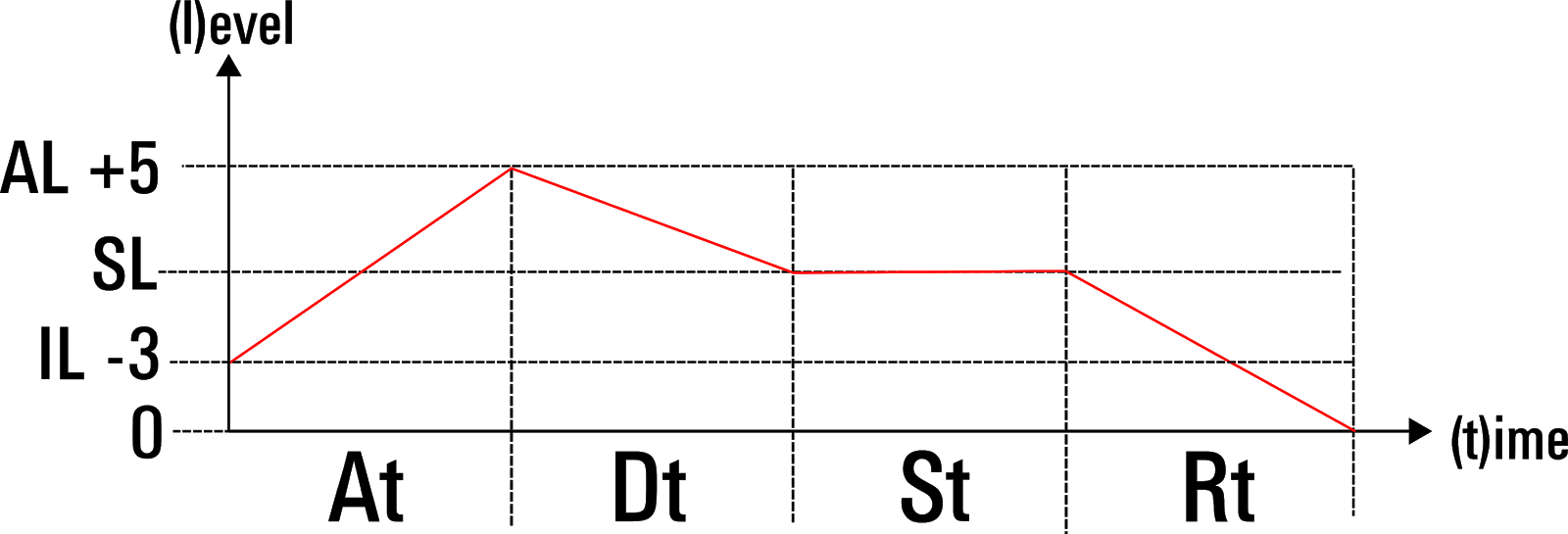
CS Filter Envelope
The CS-80 VCF has an ADR envelope with two additional Attack settings. The missing Sustain setting is actually determined by the combination of VCF cutoff frequency (VCFc) and Brilliance. The two additional settings are Initial Level (IL) and Attack Level (AL). IL is a setting below the Sustain level(Sl) and AL is a setting above it. When an envelope starts the Attack portion increases from a level determined by Sl minus IL. It then rises past Sl up to AL over the Attack time (At) period. As normal, it then decreases over the Decay time (Dt) to Sl, where it is held until the key is released and decreases down to 0 over the period of the Release time setting (Rt).
Curve Swerve
What type of curve is the CS-80 using for this envelope though?
This is the block diagram reprentation from the service manual:

That look like attack is linear, decay might be exponenetial and the same for release.
But there are notes on the special Yamaha IC that generates this envelope . What does that say?

Those all look like inverse log curves! Hmm! Well, then what about the Service Notes on tuning etc?

OK. that's different again. Someone must know!
User manual? No, unless they are all linear.
The Arturia CS-80V manual?

Well, that could be righ, but I need corroboration.
Gordon Reid? Umm, just a comment about the GX-1. And that envelope?

Now come on!
Let's try another clone of the CS-80 - Deckard's Dream
I can't find anything. It's created digitally though.
It's getting annoying now.
Eventually, checking the output of the CS-80V convinced me that the curves are log. Moving on!
CS Levels
This combination can be rather confusing to start programming from. In general, setting Brilliance to Full and then adjust VCFc to Low is a good midpoint, but if you want to start adjusting from there it's easy to lose your place.
One way to get a normal ADSR envelope is to set Brilliance and, VCFc to
half and AL to +5 IL to -5. The combination of middling Sl with maximum
IL and AL gives the classic shape, but finding a good balance can still
be difficult.
Some sort of responsive diagram, showing the levels as in the above diagram would be nice.
If both IL and AL are set to 0 then there is no AD VCF envelope. Not just no Attack portion, because there is nothing to increase from or to, but no Decay either, because there is no AL to decay from. In this case, the envelope starts at the setting of VCFc + Brilliance, i.e. Sl, and if there is a Release setting it will fade away in Rt to 0. The Sustain level is the whole envelope until release.

This arrangement is a nice feature on the CS synths, but it relies on the envelope being told what the Fc level is. This then sets the Sl and give a reference from which to set the IL and AL.
To do this in Eurorack is not impossible but it's not straightforward and it would use up a few cables and probably more than a few modules to get it to work in exactly the same way.
It does not need to work in exactly the same way though. The main advantage of the IL/AL is not the AL. If a lower level of attack is required then this could be achieved easily with attenuation. The real problem is the IL. Nearly all envelopes start and end at the same level, but what are the other options?
Envelope Options
The other options fall in to three catagories
1) Very expensive modules that do anything you want with voltages, like the Rossum Electro-Music Control Forge >£400
2) Mid-priced multi-stage generators like ALM Busy Circuits Quaid Megaslope or Mutable Instruments Stages > £200
3) Ladik C-216. £55
Control Forge is complete overkill, so let's look at the others.
Ladik C-216
Only
the Ladik C-216 delivers a dedicated envelope generator with IL setting. Is
the Ladik C216 everything I need to replicate the CS filter envelope?
It
certianly appears to be! With a bit of attenuation and/or some
decisions about how to set the filter's cut-off control even the AL type
behaviour can be achieved. Other notes in it's favour is that it is
cheap (at that price two or three would not be extravagant!), low on HP
count (4HP) and power consumption.
Up Stages
Stages is more reasonably priced than Control Forge, but might still be too much for my needs. If I did get Stages I'd want to do more with it than just envelope duty. My thinking is to have modules dedicated to the SS-30M, more or less, and Stages would be tied up completely when running duty as an IADSR.
Setting up Stages for IADSR is even in the manual.

Stages has everthing and more that I need. It has just one competitor.
Megaslope
ALM Busy Circuits' Quaid Megaslope would also fall into this trap of being too much for my needs, but it appears to get closer to CS-80 functionality because it has control over the destination level, as well as time, of every stage. It also has CV control over both parameters and that would allow for inputting a Sl CV and offsetting the same voltage for IL and AL inputs.
It would go like this.
| Stage 1 | Stage 2 | Stage 3 | Stage 4 | Stage 5 | |
| Env | Attack | Decay/Sustain | Release | - | |
| Level | Sl - IL | Sl + AL | Sl | 0 | 0 |
| Time | 0 | At | Dt + Sl | Rl | 0 |
| Slope | N/A | Log | Log | Log | N/A |
So?
I just decided to buy the Megslope. It's an expensive sledge hammer to crack the Yamaha CS envelope nut, but of course I'm going to use this for more that just that.The full CV control sold it to me over Stages.

Saturday, July 18, 2020
AteOhAte Toms
This post has now moved to https://norgatronics.blogspot.com/2021/11/ateohate-toms.html
Monday, June 22, 2020
Yamaha CP30 by Knobs & Switches
This is just a nice overview of the SS-30's electric paino cousin, the CP-30.
Sunday, May 31, 2020
YAMAHA Japan Catalogues with the SS-30
Over at this website there is a whole load of Japanese brochures for all kinds of musical instruments including YAMAHA keyboards. The SS-30 debuts in 1977 and then appears for two more years. By 1980 it was gone though.
1977 Catalogue
The cover stars, including SS-30.

The SS30 page

The family portrait

1978 Catalogue

1979 Catalogue

Sunday, May 24, 2020
Fun With Filters (Pt.3)
The Might(y) Wah!
Now that I have built the filter module I showed in part 1 of Fun with Filters it's time to take a closer look at it. I decided to call it YAMAWAH and in a later part I will show you th finished article with a printed panel.You will recall that I sawed off the end of a board from the Yamaha B75 organ and the offcut is the Brass Wah section. Obviously, Yamaha did not provide any details of this filter, other than to say that it's a wah effect for the brass voice of the. Also, I have not been able to work out what filter topolgy the iG02611 VCF chip is, so I could not easily guess what the filter type actually is from the schematic alone. Does it 'wah'?
Blessed Plots
When I was first experimenting with the filter I just noted that it was some sort of low-pass a that it rolled off around 10KHz, but I didn't get any further or measure it.The following is a brief look at the filter response curves comparing with the Roland 521 filter module. I used a white noise source from the Mutable Instruments Kinks module. All the traces are from WavePad and I recorded 5 seconds of audio in each case before plotting the spectrum.
Here's white noise as it comes from my MI Kinks module
 |
| White noise from MI Kinks |
Here's the same noise through the YAMAWAH with the cut off frequency at maximum - 100%. As you can see there is a major resonant peak. This took me slighty by surprise, but then I realised what was going on. When I was first experimenting I use a spectrum analyser VST in Cubase to check the response. In that case there was no peak evident. Couldn't really hear the peak, although I did note a bit of 'bump' when sweeping through frequencies and it was obvious that something else was going on.
 |
| White noise through YAMAWAH VCF set to 100% open. |
Contrast that with the same white noise passed through the Roland 521 VCF module in LPF mode with resonance set to 0 and the cut off frequency set to 7/10
 |
| White noise through the 521 VCF set to 70% |
And now the same but with the resonance set to 5/10
 |
| White noise through Roland 512 VCF cutoff 7/10, resonance 5/10 |
Now setting the YAMAWAH cutoff control to 3 o'clock. There is still resonance and the peak has moved down to around 4KHz
 |
| White noise through YAMAWAH cutoff set to 83% |
So far, it was much as expected. When the YAMAWAH cut off control is set to 12 o'clock something strange happens though. The resonant peak is around 450Hz, but over at other end, from 4KHz upwards there is an uplift!
 |
| White noise through YAMAWAH set to 50% cutoff |
Moving back to the 521, a similar cut off frequency setting (4/10) look like this. Which is exactly what you'd expect to see in a low pass filter.
 |
| White noise through Roland 521 VCF set to 50% cut off and resonance |
Back to the YAMAWAH, and here's the setting at around half past ten.
 |
| White noise through YAMAWAH set to 33% cut off |
And at fully counter clockwise you can see there's been almost no change in the spectrum. In fact the cut-off frequency only seems to take effect from half past ten and upwards. This suggests that the control voltage is onlt effective over aroudn 2/3 of the Vee supplied to the iG02611, or about 8V of control voltage.
 |
| White noise through YAMAWAH - cut off set to 0% |
Finally, let's look at a squqre-wave into the YAMAWAH. This is highly coloured by the 10KHz maxium cutoff frequency and the resonance.
 |
| Square wave through YAMAWAH VCF |
Learnings
Resonance
The fact that the YAMAWAH is resonating proves that resonace is possible without connecting the C1s and KO/KN pins to C3, which is already fed back to the input. It makes me think that the connection between C1s and KO/KN is responsible for part of the resonance and if I break this connection the resonance will disapear. Adding a variable resistor between these pins could then lead to a resonance control.I experimented with connecting C3 to KO/KN and seperating KO/KN from each other to no great effect, but now I'd like to return to this again.
First this is what happened when I disconnect the C1s from KO/KN. The resoanace peak disapears

And then at 50%

And at 0%

So, it really does seem that this is a notch filter. I suspect that changing the caps will move this around.
Anyway, back to resonance and adjusting the amount of current from the C1s to KN/K0 makes no difference. It's either on or off. Instead I again seperated KN from KO and that too kills the resonance. So, then I added a 100K variable resistor between KN and KO and now I have variable resonance!
Here's the plot with the 100K in line between KN and K0. There's still a bit of resonance compared to open circuit and the cutoff frequency has shifted a bit.

Here is the plot with 50% resonance - 50Kohm - and the peak is more noticable

And so I now need to add a resonance control!
Here's a video with a demonstration of the resonance control being tested
High Pass?
The second interesting thing about the plots is that almost band-stop behaviour as the filter cut-off moves down. I have been hoping that the iG02610/11 might be suitable for setting up as a high-pass filter as well as a low-pass and that behaviour makes me think that maybe it is possible.It also reminded me that I had made a modification to the C2 pin. On the B75 the pin only has a capacitor to ground. On the CS-01 that pin is connected to Vee by a 10M resistor. I didn't detect and difference by adding this, but now I'm starting to wonder.
Well, I simply removed this resistor and nothing happened. The up-lift was still present, so whatever is going on it's not that resistor. I will have to start chanaging capacitors if I want to figure this one out!
Tuesday, May 19, 2020
Fun With Filters (Pt.2)
In the first part of Fun With Filters I chopped out the Wah Brass part of the YAMAHA B75 organ and made a low-pass voltage controlled filter module out of it.
That was quite satisfying, but there's more to tell and maybe more to do. There were two IG021611 chips in the organ after all and the module I built is not really the filter I think the SS-30M needs. But what does it need?? Ideally a YAMAHA filter. That would be the ideal companion, don't you think?
CS Filters- IG00156
As noted before though, each CS era had it's own sound. The IG00156 was versatile. As a multimode device it had LP, HP and BP outputs, but the different synths it went into had a range of colours. Even if I got a chip, which colour would I choose? Or could I design in options to use different colours?
The IG00156 is included in the Yamaha IC Guide, shared by Loscha many years ago. Searches for such a guide invariably lead to this revision. I have seen mention of a huge one from 1984, but it wasn't scanned in by the owner, and the trail is very old and cold now.
What's perfect about this guide is that it shows a block diagram for the IG00156.

This block diagram shows clearly that this is a standard arrangement for a state variable filter.
There's more on this design here: https://www.electronics-tutorials.ws/filter/state-variable-filter.html
The state-variable filter was first used on the early ARP synths and then the Obeheim SEM and is actually known as a Kerwin-Huelsman-Newcomb topology.
Gotharman CS Filter Module
Some years ago now, Gotharman used to make a CS Filter module which you could fit your own Yamaha IC to and get the filter sound of the CS range of synths.
https://www.modulargrid.net/e/gotharman-yamaha-cs-filter
http://www.gotharman.dk/Eurorack_CSfilter.htm
This was specifically designed for the the IG00155/6 ICs. Here's what they say about each part:
- IG00155 will NOT work as a direct replacement for IG00156.
- IG00156 has a sharper resonance than IG00155.
- IG00155 has more bass boom than IG00156.
These chips sell for around £70 and are getting scarcer by the day, so Gotharman stopped making their module.
I would quite like to get one of these modules second-hand and be done with it, but that would be expensive and they are rare. Or I could design my own version, but that would require spares of that already rather pricey chip. Also, using up much sought after parts feels a bit wrong when they could be keeping CS range synths alive.
If I'm not going to take an IG00156 then it's not really going to be a CS filter.
For now though, I'm going to focus on another YAMAHA VCF.
IG02610/11 VCFs
Inside my disembowelled B75 were two IG02611 VCFs. They are pin-for-pin with the IG02610 and the service manual references the '10. I assumed the '11 was an improvement for reliability or some-such, but I then find that the C-605 uses both '10 and '11 parts for different modules and pre-dates the CS-01. In any case, they are apparently functionally identical.
The first thing to note about the IG-2610/11 is that there is no known datasheet on the internet at the time of writing.There's no IC guide with it in, no block diagram and only service manuals' schematics to go by.
I shall have to reverse engineer the design and connections of the IG02610/11 from these schems and see what I can figure out.
CS-01
The first thing to note is that it's not clear as I type this what kind of filter it is. From the fact that it was used in the mark 1 CS-01 I know it is a 12dB design and can be used as a low-pass filter with resonance. The CS-01 only had two fixed resonance settings, but that can be replaced with a pot to get a variable setting.
Other things of note:
- The pin 1 'IC' is clearly the cutoff setting
- Input Control?
- GO is the output, but is it paired with GN?
- Similarly, there are pins KO and KN,
- G & K? What are they?
- O? N? Output?? And what? 'iNput'?
- The resonance is an interaction between the input signal (clearly where the signal is fed back in to, C3 pin 14, KN pin 11 and then K0 pin 12, C1 & C1' pins 3 and 5.
- The resonance amount is partly determined by how much of KN goes back to KO.
CS-01 MK II - IG05630
Before I go on, there is another YAMAHA VCF chip to note.The CS01 mk II uses the IG05630 24dB filter IC. This is a 20-pin device and is properly labelled so the pins make sense. It's also clearly state variable, with outputs for LP, HP and BP filtering.

This chip is evidently the successor to the IG00156, but now they have caught up to the idea that 24dB is the way to go! Of course, this was just at the time that YAMAHA were about to kill off all analogue synths with FM. I can only find two hits on the whole internet for this chip ID, so I guess this post will be the third!
B-75 and other Electones - IG2610/11
The B-75 Electone Organ uses the IG002610/11 and I've also identified the A55N, C-55N and C-605 hosts. These organs are all 1981 models. The SK combo keyboards and Electones from 1980 all seem to use the IG00156, so it looks like Yamaha switched away from the '156 around this time and IG002610/11 took over. But, was it really a replacement?The Mighty Wah!
The 2610 is mostly used in wah modules. Wah-wah is a normally a band-pass filter, so this gives me a glimmer of hope that this VCF can be configured as LP, BP and HP. Ideally, I would use one of the two chips as a LP and the other as a HP filter.Yamaha advertising from the time is quite vague on what they mean by a wah though (https://organforum.com/gallery/albums/userpics/78173/Yamamha_C-35_C-55.pdf)

You can hear the exact effect in this video of an A55N
I am not convinced that what you're hearing there is a BP filter, and the description of "swelling" is not typical of wah. The more I look into this, the more it seems that 'wah' was used to refer to low-pass and well as bandpass filtering.
In the Electone's service manuals the IG002610 pinout labelling is quite different to the later CS-01.

The changes are:
- Pin 2 is now ICD, not NC
- KO & KN and now F1 and F2
- GO is now simply OUT
- GN is mislabelled in this diagram and in the schematics is now NF
 |
| B75 Rhythmic Wah |
 |
| B-75 Brass Wah |
The most interesting thing is that whilst on the CS-01 the IC pin 1 is the input for the cutoff frequency control voltage, and the ICD pin 2 is 'NC', on the B-75 IC pin 1 is tied off to the supply rail (via a 3.3M resistor) and the control voltage is being fed to ICD pin 2.
Guessing a little wildly, if the wah circuits are bandpass filters then does tying the IC pin to the supply make the 2610 BP mode? Well, in the (definitely) LP mode of the CS-01 ICD isn't connected to anything. I sense this is some sort of key to the behaviour of the 2610, but my guesses are not grounded in anything definite.
Inside the 2610?
We know that the 2610 is a configured for a two-pole, 12dB response on the CS-01, but there's no similarity with other VCF ICs.
The SS16124 is a modern VCA chip which can be used for VCF designs. Studying this application note provides many details on filter designs which use Operational Transconductance Amplifiers (OTAs) http://www.soundsemiconductor.com/downloads/AN701.pdf
Cascading combinations of these OTAs paired with Op Amps in Sallen-Key topologies creates higher order filter designs.The section on resonance and feedback is most illuminating, if you need to design such a thing, but there's precious little to compare with the IG2610/11.
Back to the 2610/11 and the main thing I have noted about the implemntations in all the schematics is that C1 and C1' are always tied together and with KO&KN / F1&F2.
Trying to make more sense of this I redrew the CS-01 schematic with a simplified block for the IG26010.
 |
| Simplified Schematic of CS-01VCF |
It's easier to see now what the relationship between C1/C1' and the K' pins is and how the external components work together.
GN and C2 are both decoupled to ground, whereas C1/C1' appear to be part of the active filter. As the C1s do not run direct to ground there is some clue about what the filter topology in this chip is.
T?
Searching around for other VCF designs I found Ray Wilson's design on Music From Outer Space for a VCF using half a twin-T design.http://musicfromouterspace.com/analogsynth_new/EXPERIMENTERBOARD/page3.html
Ray says "...the "active" element in the active low pass filter..." "...is essentially the low pass half of a twin T active filter."
This is relevant because of two things. Firstly there are a pair of matched capacitors which are tied together and secondly further investigation leads me to a mention of 'k'.
The twin T design is actually a notch, or band stop/reject, filter. In some sense this is like the gap between a low pass and high pass filter. If the cutoff frequncies of the LP and HP are close, the space between them is a narrow band of frequencies which is stopped. Therefore a basic desgn would be simply an LP and HP where the input passes through both in parallel and both filters stop frequncies passsing in a band where they cross over. The twin-T has another trick which makes it perfect as a notch filter. The HP and LP outputs are 180 degrees out of phrase at the notch frequency so that when their outputs are mixed the is a complete attenuation as their stop bands cross over and cancel each other out.
Looking further into these designs, the letter 'k' pops up. Here, k is the feedback fraction, set by a voltage divider. For more on that see here:https://www.electronics-tutorials.ws/filter/band-stop-filter.html
 i
iCould the IG002610/11 be a twin-T, or some other kind of T network filter? Well, it's not a twin-T if we're making a low-pass filter with it, and most importantly the low pass half of a twin-T does not have a pair of capacitors, that's the high-pass half. Umm, but why did the late, great Ray Wilson say his design was "the low pass half of a twin T active filter"? In fact there are other designs with twin capacitors that are tied together, e.g. 'Sub-Bessel' Sallen-Key, but they are all high pass. A scan through this article does not lead me to any other likely candidates. https://sound-au.com/articles/active-filters.htm
I refuse to accept that Ray is wrong, but I can't figure this out and I feel that although I'm closer to understanding thus VCF IC, I am missing something important.
Waaaaaaaah!
It pains me to have to report this, but I removed the other IG20611 from the B75, put in on a breadboard, wired it up in the CS-01 configurtion, got sound through it, and then killed it. Waaaaah! I'm pretty sure I connected the IC control input directly to the -12V rail and then, in a panic, felt it getting hot and took too long to find the problem. No more sound. No fun with filters there.This closed off the option of experimenting with the chip and I'm not keen to risk my other IG002611 which is now safely in a module that works quite nicely.
Conclusion
So far, the IG02610 and IG02611 remain somewhat enigmatic. The only things I know for certain is that the 2610 can operate as a LPF in the CS-01 and is a 2-pole filter. The use in Electones is harder to be sure, but I have a 2611 working as a LPF. On the other hand, there are some clues that there is more to these chips than that. Why would Yamaha stop making the multimode IG00156 and replace it with something with fewer features? The pair of capacitors (C1) tied together seems to indicate something contradictory about a low-pass design but I'm not able to discern what.Now, I can either make it a mission to understand the 2610/11 ICs or just drop it and move on. Frying that spare chip means I'd have to buy a new one, either as part of another organ or standalone (at higher cost price!). I'm not keen. I think my journey with the chip ends here.
I still need a good filter for the SS-30M though. What to do?
Sunday, May 17, 2020
Fun With Filters (Pt.1)
Not So Brilliance
As you saw in the Concert Mates post I'm very much thinking about filters at the moment. The SS-30 Brilliance control isn't only not a VCF it's also not even an active filter and is in fact just a single capacitor. The SS-30 is, lets not forget, a strings synth and not a proper synth.The SS-30M though is a not only M for MIDI it's also M for Modular (where possible) and one of the enhancements I've recently added is a send-return (or insert) for each voice section. That means I can insert a filter and play that paraphonically just like in those video in the last post, but as part of the SS-30M signal path and straight into the Orchestra effect.
I have a bunch of different filters at my disposal too. Not to brag, but, as well as the Moog MG-1 filter I can call on the filters of the Roland MC-202, System 500 & System 1M and the Mutable Instruments Braids, and also the 303 clones from Freebass (MAM) and Cyclonic, which are all very much in the style of the Roland sound, or thereabouts. I've also got a modified Korg Monotron which can serve as a filter too. Nothing from Yamaha though.
I do have a CS1x and a CS Reface. Both are digital, of course and neither has a filter input.
I Have No (YAMAHA) Filter
Eurorack are modues exist for just about any style of filter you could want. Roland style, Korg and Moog, Oberheim, EDP WASP, Polivoks, EMS, Steiner-Parker, ARP, and so on.
Look for a Yamaha style filter and only three options exist. Studio Electronics SE88, Old Crow's RR480 and the Gotharman CS. The SE88 is a full-featured, several hundred dollar module that takes the CS-80 filter design and runs with it. It's based on the SE Omega CS-80 filter board, which is clearly a standard set of OTA and Op-amp ICs. The Gotharman used actual Yamaha chips, which you had to find yourself, and was made in very limited numbers. Old Crow's RR480 is also a recreation using standard components, but it's DIY only.
The Yamaha synths almost exclusively used a single VCF chip - the IG00156. This was the core of the Gotharman module. The CS range of synths all shared a common chip, but the overall sound changed over the years. By adjusting the external components it was possibe to change the character of the filter. It's not clear which one the Gotharman went with, but I guess the CS-50/60/80. The SE88 and RR480 recreates the IG00156 from first principles somehow, but no-one would really know exactly what's inside that chip now, so it's just a good guess on their part.
I had nothing to hand though.
Organ Transplant
So, I went to my garage to look at the organ donor.
 |
| Wah Brass Filter from B75 organ |
I found that my B75 Electone organ also uses a couple of custom Yamaha VCF ICs. These are the IG02611. Some Electones did use the IG00156, but by 1981 only the
wonderous CS-70M was using that part. The IG02611 has a counterpart, the IG02610. The 2610 and 2611 are apparently the same, but there is very little info on them so who knows! The 2610 is used in the dinky little nephew of all the CS synths, the CS-01. The filter gets respect but no-one is doing much to recreate it in Euroland.
Anyway, this is a vintage Yamaha VCF and I have a couple on hand, so what shall I do?
 |
| Removing the boards |

 |
| Brass Wah section |
On this board the Wah Brass filter section located at the end. So, I decided to saw it off!
 |
| Dirty off-cut Wah Brass filter section. |
 |
| Clean board |
 |
| Patio Electronics |
 |
| Wired up |
Module-wah Synthesis
 |
| Back inside |
I tried to get a resonant feedback going too, but without success, so I decided to keep it simple and make this into a eurorack module as it was.
The control voltage for cut-off frequency into the 2610 is negative going, so the inverting op amp is needed to mirror all positive goingvoltages to negative. Eurorack signals are either positive, like the envelope in the video above, or bi-directional with both positive and negative going voltages, used for LFOs or audio. The level shift is thus needed to move all negative input voltages into the positive. The inverting amplifier is actually a summing as well as inverting design, adding postive offset to the input shifts negative inputs to wholly positive before being inverted to wholly negative.
 |
| Simulation showing positive going input inverted to create the correct negative, mirrored, signal for the IG02611 |
I was a little concerned about postive voltage input to the IG02611 and what damage it might do, but it seems to cope okay with it. The shift is more important to avoid the signal being rectified and ensure the whole wave shape is fed through.
Here's the schematic (note green and red highlights match with the trace above).

Other features include an attenuator on the audio input and and LED to indicate negative input voltage. This has a slight impact on the current being fed to the IG02611 and adds a little proctection. A blocking diode would stop any postive going current to the IG02611, but I did not want to have any voltage drop across the input.
So! On with the construction.
 | |||
| Module construction |


I used Front Panel Designer from Schaeffer to lay out a panel design and printed it to paper to check the fit.

I have a 3U aluminium panel handy so I chopped off a 9HP section from the end. Then I taped the paper print-out over the panel and headed to the pillar drill.


I was a bit worried about how well aligned the holes would be. It came out fine though! A bit of filing and the panel was perfect.

I decided to add the LED to warn when the input voltage was positive in a second revision.

This completes the first stage of construction. I need knobs and some print on that panel now though.
In the next part of fun with filters I will go deeper...


Subscribe to:
Posts
(
Atom
)