All-a-board
I have found the solution to my key switching PCB worries. After the quick lash-up I did on a breadboard I started to fret about what kind of permanent, solderable board to use. A standard Veroboard or matrix perfboard was the obvious answer, but only with a lot of soldering. I didn't want to have to cut dozens of wires and tracks and link everything together by hand, or rely on solder links. I also wasn't keen to design custom PCB. Apart from the costs the learning curve for creating a PCB is not one I wanted to commit myself too. If only there was a PCB just like a bread board, I thought. Well, apparently, there are! There's several on the market in fact, but I found one that matches my needs the closest.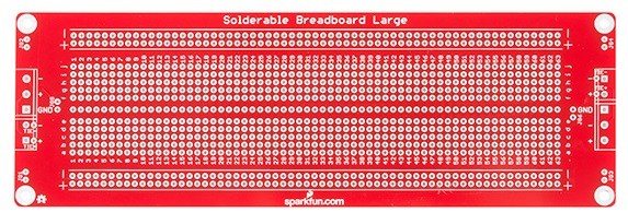
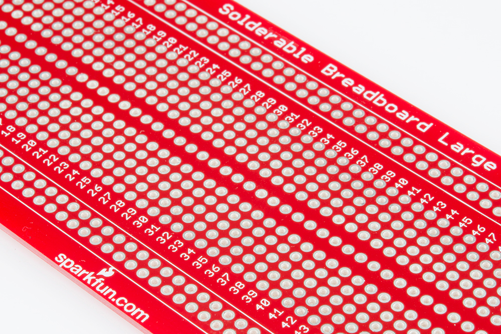
This is the SparkFun Solder-able Breadboard - Large PRT-12699
"a real FR4 fibreglass board, with soldermask, plated through-holes, and the layout duplicates the connectivity of a solderless breadboard"
You can lay this board on top of a breadboard and insert the components through the PCB to test everything as normal. Then you can lift the PCB up with all the components already in the right place and you just have to solder them in.
Features/Specifications
- 63 split rows
- Like the breadboard there's "twin rows of 5 holes each, spaced 0.3" apart, to accommodate DIP ICs."
- And there's an additional line in between the rows, but I might not need that.
- The holes are 0.1"/2.54 mm pitch (apart)
- The hole size is 0.040"/1.016mm
- The rails can be hooked up at either end
- and there's layout for terminals.
- See the Hook-up guide
Board Layout
I will need two of these large sized boards which will accommodate twenty-four and twenty-five key switches. With 16-pin, four-channel opto-isolators there will be three per octave (with one extra on K1 for the extra ). That's six 16-pin ICs per board needing (6 x 8) forty eight rows. K1 will need an additional single-channel 4-pin device. This will leave room to spare on both boards.
I might use some of this extra space for power rail circuit to the MTP8. A regulator is all that's needed if I can use one of the rails from the SS-30 supply. But that's another post...
The design then is simple. Every other pin on the opto-couplers will be an input or output wire and the alternates will be a resistor to one of the rails. What could be easier?
I have created a diagram of the layout in Excel - here's the first board. Note that as this has 25 keys I'm going to reuse a spare connect on the connector and then have to cut a track (column h, row 9) on the board and link it to the correct one.

Getting A Good Connection
The only construction concern I have is how to get the wires to the board. The 8 strand wires from the K boards are around 0.7 mm with insulation but the conductors are approximately 0.5mm. That's probably 24 AWG or maybe less.
The options are:
- Solder wires directly through the PCB holes
- Use some sort of pin or tag soldered to the board to solder them to
- Terminal blocks to hold the wires (screw or spring clips)
- Use some sort of IDC connector
- Solder the wires to another smaller board which is connected to the main board with some sort of male to female headers.
Wire through the PCB
The simplest and easiest option is to push the end of the wire through the hole on the PCB and solder like a component leg. The main drawbacks of this approach are that if I need to de-solder it there is more stress on the holes. Also the wires will probably be subject to stresses during construction and maintenance which could break off and needed re-soldering - as I have seen time and time again on the original boards. I could probably mitigate the stresses quite a lot by threading the wire through the holes. Including the rails there will be 5 available holes to go through and the stress on the join between wire and solder should be eliminated altogether.In one's cups
On the K-boards and G boards the very fine wires are soldered to pins with cups (or 'solder wells') in them. The parts list is a bit vague here and I don't think there are even listed.Here's a satisfyingly detailed piece of vintage instruction on soldering such terminals.
Digikey (for example) list a part like this as PC PIN receptacles of type solder cup . The solder termination is like those you find inside connectors (DIN, Centronics, etc. see video above.
I can also use the threading technique to remove tension so there is double the advantage over simply soldering through the board.
One downside of this approach is cost. The ones at Digikey come out at over £40 before tax for the number I need. I can also see the potential for a lot of work there too.
Terminal blocks
Avoiding soldering the wires altogether is another option. Screw and spring clamp terminal blocks could be fitted to the boards and are relatively cheap. Strips of 12 can be had for as little as £1.70 before tax.
This makes disconnection a very easy job compared to soldering and again there is strain relief possible.
On the whole though these are not my favoured choice. The thin wires from the K boards may not hold in the clips very well and I'm not a fan of these sorts of terminals. That said, the MTP-8 uses these and I'm not currently planning to replace them.
IDC Connectors
IDC connectors are a possibility because you can get the wires into the connector without soldering or paying for fancy crimp tools*. For the kinds of wires in use this might be a good option. As the Molex notes, err, note:"overcoat seven strand cable is the easiest and often performs as well as solid wire."Now, because each connection is going direct to the optocoupler ICs's pins via the board, and I don't want to cut any tracks or add bunch of link wires, it will need to be double spaced (2 x 2.54mm) 5.08mm. Most IDC is single spaced at 2.54mm though. If you want 5.08mm spacing the pins are bigger because it's designed for higher current purposes. This is a drawback of using a prototype board. I'm looking for a connector that will match the board not designing the board around the ideal connector.

I can solve this by getting one that is double length and then using half the contacts though. That then creates an issue of sourcing the right part as the longer ones with more contacts have more limited options. For example you might find a 24-way single row IDC female header, but it's probably for the wrong wire size, or no-one stocks it in quantities under 100. Also some of the more fancy solutions will be less cost effective if they are 50% redundant. For example there are AVX parts in the 8284 series which are almost ideal but the total cost would be over £100!
* Why are crimp tools so eye-wateringly expensive anyway?
Other options
There are other options including replacing the existing wires with ribbon cable somehow so that it's a snap to plug then in and out again. I really don't think there's a better option than those above though.Conclusion
The MTP8 has terminal bloc connections so I don't necessarily need more at the other end for those wires. Also, I will use fatter, stronger wires for those connections so that will probably be fine to solder through the board holes directly.
The thinner wires from the K boards are the bigger concern.
They are already soldered at the K-board end, so I would prefer not to do it at the other too. Once they are soldered in there's no quick way to disconnect if needed. However, because they are so small, even after tinning the ends with solder then may not hold in clamps very well. I would probably have to add a pin to the end of each which will be tedious to do.
Therefore IDC is the best way to go (short of crimping) and I eventually decided to get these connectors - Autocom from Stelvio Kontek - available from RS Components
Autocom HE14 90° IDC Connectors
- Single row IDC connectors with right angle exit for flat or single wire cables
- No special preparation of cables required
- Can be assembled by hand
- Double blade contacts
- Rated at 3A/1000V
- Flammability rating UL94 V-0
 |
| 12-way Autocom Connector |
These come in the correct pitch of 2.54mm and in single rows. Individual wires can be inserted in each hole and then the two halves are simply squeezed together.


Any 2.54mm pitch header would probably work but they come with their own range of headers which key in to the connectors.

1 comment :
Thanks for sharing this great information on your blog it seems to be more interesting and useful.
Post a Comment