>
YAMAHA
STRINGS
SS-30
RACK-MOUNTED WITH MIDI
MIDI STRINGS

Saturday, May 26, 2018

Individual Outputs

In the Amazona.de article by Costello, my interest in modifications was piqued by his desire to have individual outputs for each voice - Cello and Violin.

"Then you could combine almost dry cellos with "wet" strings. Even for wacky phaser and flanger effects would offer a separate decrease. Unfortunately, it is not. As a real chorus fetishist, I like to use the boss chorus CE1, which has the charm that the chorus pulls the signal into the stereo width. And of course, the Yamaha SS-30 sound also blends in beautifully with a nice phaser like the Electro Harmonix Small Stone or MXR-100. But you can also experiment with flangers and Leslie effects. And a good reverb is of course mandatory."

How can I do that? Easily, actually.

Butcher's Blocks

 Sometimes a modification requires a certain amount to of butchery - removing and replacing parts and so forth. Other jobs are a simple matter of adding a wire.

Below is a section of the SS-30 block diagram.


 All the outputs from the G boards are mixed together in the first block. These sub-circuits are call 'Mixing Amp and Filter' and produce Violin, Viola and Cello voices. These create the five voices available to select on the front panel switches.

The next block contains two 'Pre-amps' which actually just mix the five voices into Violin and Cello which are then set to the 'Brilliance'filter control.

The final block you can see here contains a pair of buffers, which are common-collector amplifiers. After the these buffers, the two voices are switched and mixed, without buffering, for the Orchestra effect.
In other words, after the buffers the two signals are combined and if I try and tap off individual outputs here they won't be, well, individual.

Buffer Zone 

Therefore the ideal place to obtain the individual voices from is just after the Brilliance filter and before the buffers. The outputs will still be subject to the Brilliance setting and not mixed, which is perfect. And, because the signals go through the Brilliance controls there are already wires going back from these potentiometers and easy access to the signals.


Which it are - line-level man!

What's less clear from the diagrams above is the voltage levels at each stage. For the individual outputs I need line-level audio, like the main output.  But what is that level and what is line-level anyway?

The SS-30 manual quotes the output level as:  

OUTPUT . . . . . . . . . -20dB/600Ω

And here's the schematic of the output.  


600 Ohm isn't a standard resistor rating so the circuit designers used the nearest - 560 Ohm.

Up-to the late seventies professional audio was based on telephone standards. 600 Ohm was the stated used for that equipment such that the output impedance (in-line with the signal) matched the input impedance (across, and in parallel with the input terminals). For transmission over long distances this was necessary but eventually this was abandoned for audio.

The units of measurement were for mW of power expressed in decibels as dBm. In this scheme 0dB is 1mW of pow err into a 600 Ohm load.
The SS-30's "-20db" will no doubt mean -20 dBm, which is 0.01mW into 600 Ohm. Again, that's useful for transmission over wires miles long, but just confusing for audio electronics, where the voltage is what matters. Still, they stuck with it for professional audio and made it even more confusing by using dBu. Electronic and communications engineers (like me) use dBu for mico-watts power (u being the greek letter mu, the prefix for micro) but audio engineers call dBu - decibels unloaded.

Here's what Wikipedia says:

"The decibel unloaded reference voltage, 0 dBu, is the AC voltage required to produce 1 mW of power across a 600 Ω impedance (approximately 0.7746 VRMS)."

Which is to say, it would be delivering 1mW into a 600 Ohm load, if you still had such an input. The voltage for 0dBu is 0.775VRMS though, no matter what the input load.

Taking the load off

When the 600 Ohm standard was dropped it was replaced by so called impedance bridging. In this scheme the input load impedance is much higher than the output impedance. This means the voltage is maintained whilst not sourcing so much current from the output. More current means more power but that's not what is needed.
The higher impedance at the input reduces the current load carried from the output to such a degree that it is considered unloaded - hence dB unloaded, dBu.

So what is the voltage of the SS-30 output? Well as the wattage of -20dBm is 0.1mW, which is one tenth the reference wattage of 1mW the voltage is one tenth  the refernce  - 0.0775V RMS or 0.11 V peak and 0.22V peak to peak.

That seems low but the reference level is, well, it's a reference. It's based on a sine wave, not necessarily a good indication of the noises coming of a synth.

Wait, what was I talking about?

Individual outputs

The voices each have pre-amps before the buffers and the output level here is significantly higher than the main output.
This is to be expected. Although there are amplification stages after this point, there is a fair bit of loss to make-up, so it needs to start at a much higher level.

When I measured the signals at this point with my scope I got something like 3 Vpp. i.e 1.5 Vpeak and 1V RMS. That's 2.73 dBu and to bring it in line with the main output it will need a fair bit of output impedance. If a typical line input impedance is 10KOhm then to reduce the level down to the same as the 0.11 V RMS of the main output I will need an output resistance of 10 times 10KOhm.

Well readers, I didn't think about any of that when I was trying this. No, I just tried a few resistors out until I got a level that sounded about the same as the man output. It was 100KOhm so it looks like my post-hoc analysis was right! 

Just putting it out there.

Individual outputs are a cinch, so this modification in definitely in. When I was experimenting I also detected a difference in the sound. The tone was clearer, as you might expect, but the attack also seemed sharper. At least that's how it seemed. I'd like to test it again and make sure I wasn't fooling myself.

Sources


https://en.wikipedia.org/wiki/Line_level
https://www.soundonsound.com/techniques/understanding-impedance
https://en.wikipedia.org/wiki/Impedance_bridging
https://www.soundonsound.com/forum/viewtopic.php?p=222528


Monday, May 21, 2018

Thanks For Your Input!

Putting in the input


Some things are just too easy and you wonder why you didn't just do them earlier. Attaching an external input to the Orchestra effect is one such job.

Referring back to the modification I did to the switches and depth control to have individual wet/dry mix controls for each voice...


I simply added a wire to the Violin voice's input to the mixing amp and switched off the Violin voices for good measure. I haven't replaced the Violin switches yet and I just wanted to isolate the external input as much as possible.

And, hey presto, I have a chorus effects unit!

Because the PSS-580 sounds relatively poor and because I had it to hand I filmed a demo of it with a few different presets to show how useful the effect is.
 This film is a multi-camera wonder! You can see me playing the'580 and adjusting the effects-send at one and the same time! I also downloaded Lightworks so I could superimpose them together.

The channel on the right is the PSS-580. The one on the left is the SS-30. By using the mixer I can also feed the SS-30 back into itself. This creates an even deeper effect. As you get closer to the point of howl-around you get some interesting artifacts around the attack portion of sounds too. A couple of times I push it too far.


Now that this is tested I need to decide how to implement it.
  • Input connector on the front or back panel?
  • Is it worth having an input level control?
  • Should I add a feedback control for the SS-30 so that the deeper effect can be obtained without any external mixing? 
  • Should the external input be routed in with the SS-30 voices or should it just go into the Mixing Amp with it's own channel and 22K resistor?
That was an hour's work on Sunday afternoon so in the evening I decided to try something else with the Orchestra.   

The indications are good

The Orchestra has two LFOs. One fixed at 0.6Hz and the other variable. It occurred to me recently, whilst having deep think about the user interface (of which a blog post is forthcoming), that I could have a blinking light to indicate the rate of the variable LFO. At least now that it's fully variable and not just two fixed speeds it's useful.

The LFO is generated by the IG00150 VCO. This device has two outputs, a sine wave is used for the Orchestra effect and there's an unused sawtooth which I can use to control an LED. 


With a simple transistor driver circuit and borrowing a 15V supply rail I quickly got this demo working.


I would need a small board to hold the components but this is a nice addition to the SS-30M.

Thursday, May 17, 2018

Switching Controls

Earlier this week I sepnt a bit more time fiddling with the front-panel controls.

The first job was to remove the switches I wanted to use from the donor Organ. More on that in a later post.

I also replaced the two Cello voice switches (1 and 2) with faders.


As you can see I hacked them onto my laser-cut temporaray panel. they oinly fitted the gap sideways asnd needed a bit of accommodation. The temp panel's going to be abused a bit whilst I work through this phase of the project.

The faders are from an old mixer (Starsound Dynamix 260) I got from my old high school. I binned it years ago but kept the faders. These are 10Kohm log audio 'A' type and worked perfectly!


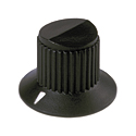
Knobs


Here's an old post I put together when I was looking for the perfect knobs to use. I have a solution now, I think but here's the research I did...


Alright! Settle down!
 Yes, we're looking at knobs.

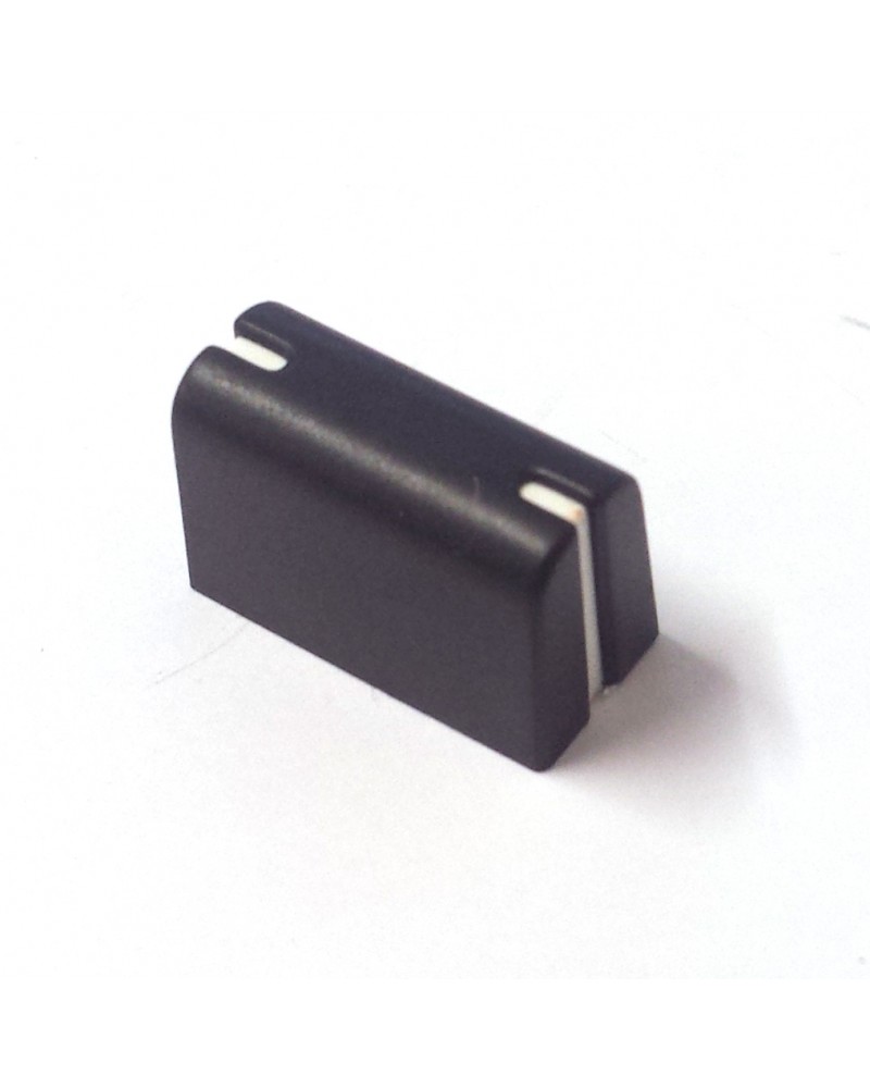
CS/SK style slider knobs 

Where can you get these nowadays?

These exact slider caps are available from http://www.synthparts.com -

"Yamaha CS50/60/80 Slide Pot $12 (larger quadrant type $14)"

That's quite a lot of dosh for some knobs if I get 10 or more, but would be absolutely pukka. I also might feel bad depriving CS owners of precious spares though..


There is a spare part for Numark mixers NS6/NS7 and AKAI APC - PT11106163-  which looks similar, but is possibly a bit bigger and flatter on top.They are definitely textured and matt and not smooth and silky like the original ones.

In context :

AKAI APC40


And then there's the mix slider - PT11106178 - for the 'Numark
V7
MIXDECK QUAD
NDX800
NDX900
NS6 :

NS7
NSFX
This looks rounder but a bit short.

PT11106178


CS style lever switch caps


The switch are caps not so available - except they may be the same as some of the Electone Organs some of which can be bought very cheap, although getting enough of the same colour would be an issue and that's a lot of wastage...
EDIT : I know have a bunch of these lever knobs from the B-75 organ I bought. They aren't quite right for faders though. The sliders have a curved travel.


SK/CS30 style knobs

Right - SK /CS knobs


Perfect Circuit sell SK knobs but they don't seem right at all.  Not U shaped knurls and strange lip on the cap. These are in fact from the Korg MonoPoly - Syntaur sell them too.


Wrong - Korg MonoPoly

Where can I find the right ones? I don't think I will. I've searched high and low and whilst there may be a plastic bin with a dozen sat in a surplus shop in Japan or the States, I can't find them.

Syntaur are our of stock
https://syntaur.com/Items.asp?Item=5093


Here's something with the nearly the right knurling - U shape -  but the base is wrong. I quite like it anyway. I think I have something similar on the back of some speakers I made when I was a lad. There are more sturdy than beautiful.

https://www.quasarelectronics.co.uk/Item/kb0295-19-5mm-6-35mm-control-knob-white-pointer

Mammoth do them too - in different colours - but manufatuer is not mentioned

https://www.mammothelectronics.com/collections/knobs/products/kp-16x15f-series-plastic-fluted-control-knob-16-x-15mm?variant=28794244295

On ebay


CS 15 smaller sliders

Part number CB811290.
These guys seem to do a similar part http://www.shokaifareast.com/Products/Pots/Slide/slide_knobs.htm

Manufacturers

Rogan

Large range - no exact matches though.
http://www.rogancorp.com/knobs-hand-hardware/plastic-control-knobs

OKW

Many and varied
https://www.okw.co.uk/en/Products/Potentiometer-Tuning-knobs.htm

Sifam

Large range of knobs - sliders fairly standard mixer and eq types.
http://www.sifam.co.uk/knobs.asp

Selco

Standard range
https://www.selcoproducts.com/knobs

Cosmo

Standard range.
http://www.cosmocorp.com/en/kcat-main.cfm

Ehc

 Huge range
http://www.ehcknobs.com/index.php?id=CK 


Coolor Caps

Fancy, candy coloured and novelty knobs - single stripe fader knobs, sold in packs too.
http://coolorcaps.com/product-category/caps/


 Even do hydrodip printed ones


Specialised synth shops' knobs

Perfect Circuit

https://www.perfectcircuitaudio.com/accessories/parts.html


https://www.perfectcircuitaudio.com/juno-106-slider-cap.html <- similar to CS/SK slider cap but not rounded.

Syntaur


https://syntaur.com/knobs.html
Have a large number of parts inclusing some real synth classics, not nothing at all for classic Yamaha analogues :-(

Grayscale

Single design - Rogan?
http://grayscale.info/index.php/?s=knobs


http://www.synthparts.com/ <- Have CS50 slider caps
 http://www.vintageplanet.nl/ (Closed)

Organ shops

http://www.mcnsystems.com/parts.htm <-No lists but lots of stuff.


Small Electronics shops

http://www.cliffuk.co.uk/products/knobs/rotary.htm
http://www.surplussales.com/ShaftHardware/Knobs/Index.html 
https://www.tubesandmore.com/products/knobs  <- Guitar stuff mostly
https://www.westfloridacomponents.com/Knobs.html <- not much stuff
http://www.mzentertainment.com/store_dr_zee_workshop_parts_knobs.html - <- Loads but nothing 'right'
http://www.electronicsurplus.com <-quite a bit - bad site though


Wholesale

http://www.ebay.co.uk/bhp/fader-knobs
http://www.aliexpress.com/popular/mixer-fader-knobs.html


General Electronics Shops

https://www.rapidonline.com/knobs
http://uk.farnell.com/knobs


Overall though I want these and I can't get them.


Monday, May 14, 2018

Orchestra Manoeuvres

I did do most of them in the hours of darkness, yes.

I’ve been thinking about and planning the power supply a good deal this week, but it’s turning into a mini project of its own and I wanted to keep the momentum up on the rest of the SS-30M.

As the weather is good and I now have an electric heater for when the evening temperature starts to drop, I was out in the garage again tonight with the aim of trying out the redesign of the Orchestra section.

You may recall that the SS-30 Orchestra effect section has four controls.

Depth - Which is actually a form of dry/wet mixer knob which goes from mostly dry to mostly wet
Speed - A switch with a fast or slow setting for one of the LFOs
Cello - A switch to route the  Cello voice to the Orchestra, or bypass it.
Violin - A switch to route the  Violin voice to the Orchestra, or bypass it.


When I wrote the Orchestration blog post I came up with a more versatile scheme with three controls.

Speed - A knob which controls the speed of one of the LFOs
Cello Depth - A knob which controls a wet/dry mix for the Cello voice
Violin Depth - A knob which controls a wet/dry mix for the Violin voice

The advantages of this scheme are that with fewer controls I get greater control. Yamaha’s designers would probably argue that the benefits of controlling the speed are minimal but for such a small cost I simply say ‘why not?’. As for having a depth control for each voice, again it’s questionable when you consider that it’s mostly an on/off choice, but I think having the greater freedom allows for more possibilities - even if you don’t always want to take advantage them.

This evening I got the new scheme working with some linear rotary potentiometers. The old controls are gone.
This was the rough sketch I did before and it’s what I ended up doing.

It leaves the dry mix of Violin and Cello from ‘Mixing Amp’ unused. Previously, some of this would have made it into the mix even when the Depth setting was full on. The depth pot was 50K so not much would have got in, but some would. Now the balance of wet/dry is done before the mixing of the voices, but a little of each will get through even when the setting is at the extremes.
I used 100K for the Violin voice but I only had a 47K left so used that for the Cello.
I’m not sure how much difference this makes, if any. I could eliminate this slight bleed through at one end if I use a pot with a switch. Perhaps so the dry mix is totally dry.

The other thing, which I didn’t consider before, is that even when little or no signal is going into the Orchestra effect there is still some noise coming out. In the original design the switches ensured that this would never reach the output. I need to do some listeing tests and think about this.  The effect is not totally clean but I didn’t hear anything untoward this evening.


Tuesday, May 08, 2018

Current Affairs & Power Couples

Current Account

A critical issue for the SS-30M has always been where the extra power for the MIDI interface would come from. If it needs to have it's own supply then there would have to be an elegant way to incorporate that. I mean, I don't want two different power inputs.

Now that the interface is working I have been able to measure the current drawn in the worst case situation of all 49 keys being pressed at once. This isn't a realistic use case but it could be a failure mode of the interface or an accidental occurrence

There's only one positive rail in the SS-30 power-supply, 15V, and that's just right for the CMOS MIDI interface so that's what I tried to use. The +15V rail has a 500mA fuse, so as long as the total current  draw does not exceed 500mA - with some headroom - I can use it to power the interface as well.
Firstly, the supply to the MIDI interface is (ahem) currently coming from my bench power supply. This tells me how much current it's supplying and when all the keys are down that's 144mA, DC. Ideally then, the draw on the 15V rail of the SS30 will be well under 350mA DC.

To measure the current there are two options. Interrupt the DC rail coming into the SS30 and place my multimeter in series there, or simply remove the fuse and measure there. There is difference though. The fuse is on the AC side of the power-supply - before DC regulation. I measured at the fuse and got around 570mA when both the interface and SS-30 are powered and all keys are on. At first I thought thatat was it and the current was too high. Then I recalled that the fuse is rated to the RMS value. The RMS value for a sinusoidal signal - which is what we get from the mains transformer - is I/1.44 (where 1.44 is an approximate value for the square root of 2). I measured 570mA so the RMS current is 570mA/1.44  = 396mA.

To be sure, I replaced the 500mA fuse and tested again. The fuse held and I have my answer: I can power the MIDI interface from the SS-30 power supply.


Power Couple

The second problem with power is that the SS30 power supply won't fit into the space left in the 19" rack enclosure. I need a case just for the PSU and then to get the power rails into the SS-30M I need a connector and cable arrangement with enough conductors.  Carrying a single rail is easy but I  need 6 conductors.
-26V
+15V
-15V
-7V
2x 0V

They also need to be rated up-to 500mA. I don't want to lose voltage through the resistance much either.

I found these connectors.


http://uk.farnell.com/cliff-electronic-components/fc684206/socket-cliffcon-shielded-6way/dp/1908694


And there's a ready made 1.5m cable assembly


http://uk.farnell.com/cliff-electronic-components/cih684216/circular-cable-6pos-plug-plug/dp/2663546?MER=bn_level5_4NP_LastViewed_3

The length is important because the SS-30M could be mounted relatively high up and the supply would likely be on the floor.

This is what Cliffcon say:

CliffCon® Miniature ZC Series

Our ZC series, miniature, locking, multi-pole, shielded connectors are available in a range of 2 to 8 pole plugs and sockets. These are primarily intended for low voltage and signal applications. Contacts are tin plated and other metal parts are nickel plated brass or Mazac. There are also 90° versions of the plug available to order.

Specification: Rated 1A / Pin - 48V max.

I'd like the 90 degree angled plug but Farnell only stock the other kind. Otherwise it's perfect! All I need now is an enclosure for the power-supply.

Wednesday, April 11, 2018

Mu-zines

I just wanted to draw attention to the incredible muzines site which is archiving old music technology magazines.

http://www.muzines.co.uk/

I haven't found a review of the SS-30 there yet - and most magazines seem to to be early 80s - but there's plenty to enjoy.

I found this quote from Rusty Egan talking to Electronic Soundmaker - Aug/Sep 1984 - about the first Visage album.

"We used everything on that album. We had a GS2, two Yamaha grands, two ARP Odysseys about three Yamaha string synths, a CS80 and a Minimoog. We used a Fairlight on that album, we had the first one that came over from Australia. Before The Steps it's Peter Gabriel going 'Waugggh, wauggh!' 

 http://www.muzines.co.uk/articles/searching-for-the-perfect-beat/3385


 And this round-up of stringers, also from Electronic Soundmaker in 1984 :

http://www.muzines.co.uk/articles/string-synths/3265

Tuesday, January 02, 2018

Attack Formation


When I wrote this post about the concept art  I said "I've assumed I can replace all switches with potentiometers".  That assumption was wrong in the case of the Attack control though. In the last post I mentioned that "it's more of a re-design job than a modification".I shall now try to explain briefly, why that is.

The SS-30 Attack control is a switch and according to the user manual :

With this tablet switch on, the rise of the sounds of the Violin system will be softened.
 Softened is the adjective because although it is slower with the switch on the change is subtle. The normal attack is not particularly hard, but the Slow setting is only slightly longer. As we'll see below when I calculate the the rise time, it's not the typical attack range setting that you get on a synthesizer.

Another bow to the string?


Billy Currie put his finger on the reason for this choice in the interview he did with GForce Software. "You were able to create the feeling of a bow" he states. I had a bit of a look around at the synthesis of bowed strings but all I could really come up with was that you need a bit of attack to stop it sounding like an organ. Fair enough, but Curie's point is a bit more subtle than that. The Slow setting provides a softer attack option which his Elka Rhapsody 610 could not. In any case, an even slower attack is not typical of a bowed string. You cannot, for example, slowly increase the volume of each string. Therefore, an even slower attack wasn't needed, because that would stop it sounding like a bowed string (or bowed strings), and a shorter attack would have the same problem.

That's the design choice Yamaha made dealt with, but what about redesigning the attack circuit? Can it be done?

Not easily, no. I had a stab at analysing this circuit before, in the post A Switch To Variable Controls. I wasn't quite correct* in the description there, but I was right that no control could easily be added. Let's see why.

*Wrong

Charging into attack

Keying Drive circuit
 In the diagram above I've highlighted in red the part which controls the attack setting. Tr24 is a transistor which controls the current that charges the 6.8uF capacitor when the key is pressed. The same capacitor discharges through Tr23 when the key is released - this is the sustain control.


The key to the attack time is the charging time of the capacitor. Capacitor charging time is constant for a fixed voltage and is the product of resistance and capacitance. As the capacitance will not change the charging time is controlled by altering the resistance.

The collector of Tr24 is common across all the keys. This node is either open-circuit or grounded depending on the Attack switch.

Attack Switch - BL is the BLack ground wire, which is fed from VR3.
 The base of Tr24 is connected to the key switch. It's normally -7V (via the supply rail and the diode D12) and then switches to 0V when the key is pressed.

The emitter of Tr24 is normally at -7V (again via the supply rail and) so, as this matches the base voltage, normally there's no current flowing through the transistor. When the key is pressed and the base is set to 0V the base-emitter junction acts as a diode and current flows across it and thus the capacitor is charged . What about the collector though?

Let's start with the collector open-circuit. In this case we can treat the base-emitter as a diode and simplify the circuit somewhat. In this case the resistance is circuit with the capacitor is 12K Ohm and 2K2 Ohm,  in series, which give 14.K Ohm in total.

Now what happens if the collector is grounded? In this case we have provided a path from ground to the capacitor directly through the transistor Tr24. When the key is pressed the base switches to 0V as before and a small current is produced across the base-emitter, but now the transistor is switch 'on' and current runs through from the collector. In terms of the resistance to ground the 12K resistor has been bypassed and the total resistance is now just 2K2 Ohm. As the resistance is lower this will produce a shorter charging time, so the normal attack setting is grounded - as you can see in the diagram above.


We can now calculate the attack time for both the normal and Slow settings.

Normal  - R = 2K2 C = 6.8 uF RC = 1.496e-2 = 14.96ms
Slow - R = 14K4 C = 6.8 uF RC = 9.792e-2 = 97.92ms

Note that I haven't accounted for the Vce voltage drop of 0.2V. With that the normal attack time is slightly longer at around 15.3ms.That assumes that the supply rail is exactly -7V and to be more accurate will require some actual measurements. The important thing is that the attack time changes from approximately 15ms to roughly 100ms for the Slow setting.

The long and short of it

Now we know how it works, what about making the attack time more controllable? Can it be adjusted to be shorter or longer? The answer is that the circuit can be modified only to make it adjustable between 15 and 100ms. The RC constant of the circuit is limited by the 12K and 2K2 resistors and no matter what you do with the collector voltage those two impedances will still be there. The attack cannot cannot be shorter or longer than the setting already obtainable, without completely changing components on all the 49 switch circuits.

With 2K2 after the emitter the minimum attack time will always be 2200x6.8e-6=14.96ms. The resistance can't be set any lower so the CR time constant of the capacitor charging will never be lower than that  If I remove the 2K2 resistor from every key circuit, and replace it it with a short-circuit, I could replace the attack switch with a 2K2 variable resistor and vary the resistance from 0 to 2K2 Ohm, giving an attack time of 1-15ms - or thereabouts.
Similarly the 12K resistor into the base of Tr24 sets the maximum attack time. Increasing the resistance between the collector and ground will initially provide an increase in the time constant from15ms upwards, but the higher it gets, the more the total resistance is being determined by the two impedanaces in parallel. In practise the total resistance will never get back to the same value as when the collector is open-circuit and the maximum attack time will always be just a bit lower than the 100ms.
The only way to make the attack time fully controllable, via the collector would be to replace the 12K resistor with much higher value - like 1M - and replace the 2K2 resistor with 0 Ohm link. Then the collector resistance would be in complete control of the CR charging constant.

I don't think I'm going to do that. It would probably take several hours, and that could still be be worth my while, however the risk of damaging a PCB track when there's 4x49=196 joints to de-solder is, well, it's not good odds.

In conclusion, where there's a will there's a way but there's no will to do this one. The attack control will remain as a switch.

Organ Donor

Which brings me to a confession. I bought an entire organ to get hold of two switches.


I may have gone too far this time. It's quite something to discard the wooden case of the SS-30 only to later by a dual-manual organ because I need a couple of switches.


Not just any switches, of course...


These Yamaha switches are just the right sort  - being black and tablet, not too large and the right vintage - to go into my front panel. There will be more about this, and the organ, later.


Wednesday, December 20, 2017

Amazona.de Article


It's nice to see the hard work researching and documenting my journey into the SS-30 get some recognition...

Der Yamaha SS-30

Every now and then I decide to Google the SS-30 and see if anything new has come up. Usually, it's just an auction, but sometimes there is a new article mentioning the SS-30.

Yesterday this came up:
https://www.amazona.de/blue-box-yamaha-ss-30-string-synthesizer/

Here's the Googlish translation:
https://translate.google.co.uk/translate?hl=en&sl=de&tl=en&u=https%3A%2F%2Fwww.amazona.de%2Fblue-box-yamaha-ss-30-string-synthesizer%2F 

Amazona is a German website dedicated to synthesisers and this article is written by keyboardist Costello. I'm very pleased to see that he has quoted this blog and credited me throughout!

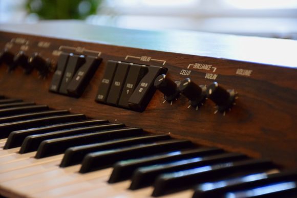
Costello's SS-30 in close-up

Found in translation


The Google translate does a decent job and it's quite readable. Even where it's a bit hard to parse it still makes sense.
"Those with the organ made rock, with the string part epic-spun "pothead music" - no play under 7 minutes."
My favourite quote though is:

"Steven Norgate dedicated his own website to the instrument, where he documents his self-imposed goal of the (very elaborate) MIDI-coding of the string synthesiser"
Don't forget about the crazy the rack mounting!


Costello talks through his early desire for a strings machine which is then rekindled by seeing Ultravox live in 1981. He is a fan.

Then he goes through the competitors and the market for stringers before getting down to a detailed description of the functions - laying out its strengths and weaknesses.

He notes that the violins are better suited to the Orchestra effect whilst the Cellos are surprisingly good without and work as a bass synth part. This is where the selection of which one to send through the effect is crucial.

He then reviews the use by Ultravox and Dave Formula and via him to the current market value and his own recent purchase. With a nod to the unobtanium chips the review is over and I have to say its the best yet - if only because I have covered most of the same ground already! 😉


Just a Limit


Let's take those limitations one at a time:


Shrill violin

I can't argue with that, but there is the Brilliance control and with the Orchestra and with a good measure of reverb it's basically fine. Costello's comparing with the Solina and other stringers - so it's all relative.

Only does strings

True. A few times I've thought about what it would take to try and tap-off a sqaure-wave voice from the dividers. Apart from the ridiculous amount of wiring involved it just isn't worth the effort though. There would be no enevelope either.

Only fast/slow control for the attack

 True, and I've looked very carefullly about how to modify that, but it's more of a re-design job than a modification. I have a whole post about that limitation in the works.

Noisy Orchestra effect

Not a problem unique to the SS-30 though. Gating and eq'ing can help. It might be possible to clean it up with some newer components, but I haven't ever thought it was bad enough to warrant that kind of intervention.

Mono only output

This is something I have thought about addressing already, in this post. It's quite possible, but will need a bit of extra output buffer amplification.

No separate output for violins and cellos.

I've only considered this briefly in the past, but couldn't see much to gain from it. Costello is clearly interested in putting different effects on each voice though, so should I reconsider it? I might. It depends on the levels, but there is an obvious place to feed the voices from, just before the Orchestra sedtion. And I'm going to be rewiring there anyway, so it makes sense...

Orchestra depth

Also, in the comments section, another person previously quoted in the article, 'iggy_pop' notes that "the depth of the chorus modulation (never enough)". As I noted in the Orchestration post the so-called depth setting on the SS-30 is mix depth, not the modulation depth. However, I can add a control for this LFO/modulation depth, but it would not increase the amount of modulation. Do I need to see how it might be boosted as well as cut?  I will take a look at the voltage out of the Phase Mixing section to see how much is being swung on those outputs.
If he was actually talking about the LFO rate, then I can probably do something there as well. The rate is limited compared to the Yamaha CS-15, which uses the same oscillator chip.


It's A Demo


But wait, there's one more treat in store! Costello has created fifteen tracks using the SS-30 to demonstrate the versatility of the old beast. Picking up styles from the likes of Pink Floyd, Genesis, Ultravox, John Carpenter, and other late-seventies influences, he uses external effects from the same era to show what the SS-30 sounds like in a variety of settings.
There is a mixture of full tracks and parts showing off certain features, such as the detune. The use of a good reverb is well noted and is something I have been considering for the long-term.

 Marvellous!


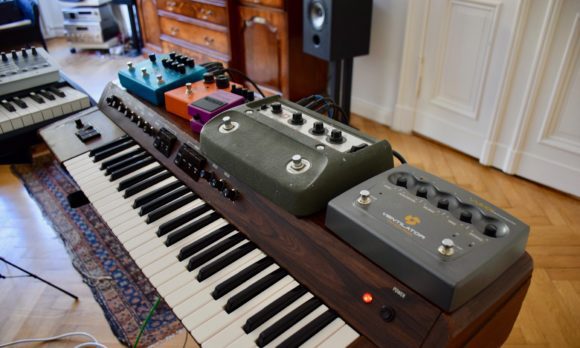
Costello's SS-30 with a bunch of vintage and vintage style FX pedals


Wednesday, October 18, 2017

Orchestration

Let's look at the Orchestra. Firstly I was interested in a new DIY product from Oakley Sounds which leads me on a diversion around the Roland Juno chorus. Then I talk about the controls I will need for the SS-30M.

Oakley SRE330 - Enhanced Stereo Ensemble and Chorus Module


I just saw this new DIY chorus project available from Oakley Sound and it got me thinking about the Orchestra (AKA Ensemble or Chorus) part of the SS-30 again.
They also used an alpha Juno for the demos, which is also kind of interesting as I have an MKS-50.

The Oakley design has 4 delays which can be stacked or and split for stereo in various combinations, It has two basic settings.
"The three phase setting replicates the action of classic string machines originally from Europe such as the Solina and Logan String Melody."
And
"The Multimode setting is designed to replicate the actions of various classic synth chorus units and string machines from Japan."
A-ha! Like the SS-30? Not quite, no.

The multimode has three settings
  • Quad Ensemble
  • Dual Ensemble
  • Stereo Chorus

The SS-30 is mono and the quad ensemble uses all four delays, whereas the SS-30 has just 3. In fact the SS-30 is closer to the three-phase mode, albeit with fewer phases.

You may recall from this post that the SS-30 has two LFOs with two phase shifters
So, that's two LFOs, although one is variable and only two phase shifts but the mixing is complex. It's not even clear from the Oakley description how they mix the phases in 3 phase mode, so I can't actually tell how they compare.

Overall it looks like a very nice project and one that I would be prepared to consider doing, but probably after the SS-30M is done.

Juno what chorus the Alpha has?

As mentioned above I have an Roland MKS-50, which is a rack-mount Alpha Juno. The chorus on the Alpha Junos/MKS-50 is apparently a different beast to that on the older Junos. Gordon Reid summed it up as "more flexible but less rich". And rich is the desirable thing, really. You can change the rate of the LFO (or LFOs?) but is that better than being able to switch between two LFOs? I would say the chorus on the Alpha is in keeping with the more restrained and cleaner sounds which were in vogue at the time. But, why is it like that?

The Alpha's chorus is a stereo-pair of single BBD delay lines. The MN3101 is the clock and the BBD is the 256-stage MN3009. And the Juno-6? The same! They use the same exact chips. There are two identical circuits, so you get stereo outputs. The JX-10/MKS70 had more-or-less the same design as Alphas too. So what was different?
The Juno 6 service manual helpfully makes it clear that there are three triangle-wave LFOs. Two at chorus speed of 0.4 and 0.6 Hz and a vibrato which is added at a lower level and runs at 8Hz. The schematic is a bit loopy by I think the same modulation LFO mix is is fed to both channels but out of phase.
On the MKS50 things are not as clear. There seems to be a single signal split into two out-of-phase signals driving the clock. The signal's origins are more obscure though. It appears to be digitally sourced from the CPU via a gate array and a multiplexer.
The gate array has a D-to-A converter built in and its here that the data from the CPU is converted into the LFO signal. On the block diagram, the multiplex is labelled as a sample and hold (S/H) and there is some kind of active filter after that - which makes sense, as there is no continuous CV to make up the LFO. It is smoothed out by the filter, I guess. The notes refer to it as chorus LFO and Chorus Rate CV.
In notes there is also basic diagram of what to expect.

Those arrows seem to indicate some sort of pulse-width is adjusted but I guess this is actually the frequency/wavelength.

It's possible to add a chorus input to the MKS-50 but there's a little debate about the wisdom of doing it and I haven't seen a really popular modification for it. Apparently there was a professional modification around, so enough people must have thought it was worth the effort of tapping into it to make that a thing. There's no info on what they did though.

Conducting The Chorus

In my mock-up, concept art panel design I had replaced the Orchestra section's Violin and Cello switches with faders. Looking back I'm not sure I knew what that was actually meant to do. As there is also a Depth control what was I thinking? Would the depth control also be required? What would the effect of the control be exactly and wouldn't those faders be pointless if the depth was set to zero? I honestly wasn't sure. And then the switches started to misbehave...

I don't  think I had ever looked at the schematic for the orchestra controls in any great detail and when the Violin switch started to behave strangely I realised it was doing more than I had imagined.

Mix Depth

To start with, in the Off position the switches bypass the Orchestra completely. In this mode the depth setting has no effect on the sound at all.

This might seem pointless at first sight. It's generally less confusing if all controls work at all times and there's no context in which they aren't having some effect. In this case the context is whether the switches are on or off and the key here is that there are two switches and two sources that pass through the orchestra effect. There are, of course, four options here and only one leaves the Depth control redundant. Still, it does return us to the question of what my two faders were supposed to be for.

Next, if one switch is on and the other is off there's a way to have one voice dry and one wet. This is why there are two switches.

If either switch is in the On position the Depth control sets the mix of wet (effected) and dry (unaffected) signals for both Cello and Violin. This means that unless one is completely off, there is no way to set the mix independently. You cannot have one at 50% and one at 100% wet, for example. Now I think I can see the point in the faders. If they controlled the amount of mix for each voice then there would be more control. However the depth control would be redundant. And yet there is another option.

LFO Depth


Referring back to the Oakley Sounds SRE330 there is a depth control there too. However this Depth control is not the mix, it's the amount of LFO being applied to the BBD. So, could I rethink the depth control as LFO depth?

There are two LFOs. And then they are mixed together and the result is three signals which go from LF board to the OR board. I could easily intercept these wires and send them through a 3-gang potentiometer. Or I could have a depth control for each of the two LFOs - but then I would have to pull up some resistor and I;m not sure it's what I need anyway.
I reckon the LFO depth would be a good change. Along with the LFO rate settings I thought through in the previous post on the chorus I'm starting to get a better idea of a more fully featured Orchestra/Ensemble/Chorus effect. 

Switches to Faders?

If that's it for the mix depth control, there could be two fader controls to set the mix of wet/dry of each voice. Can I achieve this just by rewiring the existing connections though?

Unfortunately Yamaha took a design decision which makes that harder than you would think. The switches are actually double-pole (two switches which are actioned together at the same time). The first pole, on both switches, switches the incoming Violin and Cello signals to either a mixer which then passes them on to the Orchestra, or to another mixer which then passes them onto the other pole of switches. At this pole the mixed signal either goes directly to the output stage or to the Depth control.
To be clearer if only Violin goes to the Orchestra, Cello goes to the output stage directly and Violin goes through the Orchestra and to the depth control. The depth control is then mix of the dry Violin and wet Violin from the Orchestra.
I need to somehow have the completely dry, bypass signal at one end of a potentiometers and the Orchestra at the other. The incoming signals will then be sent to one or the other, or some mix of both. Then the output of the bypass would go direct to the output and the Orchestra would also go direct and and the switches and original depth control would be completely redundant.

Looking again at the diagram I simply removed the switches and Depth control then drew in what I wanted to do. 


After the Buffer section and before the (pre-Orchestra) Mixing Amp and Mixing sections I have replace the switches with two potentiometers. I will have to experiment with the values here.
After the Mixing section I have labelled the path to the next section as 'Bypass'.
The output from the Mixing amp is split two ways. One goes to the Orchestra board and the other to the mix Depth control. Now the one to Depth control line redundant. Instead the signal back from the Orchestra goes direct to the next section where it is mixed with the Bypass signal.

I will need try this, but it's mostly just disconnecting the switches and Depth controls then adding the sliders. It's not a big job. My main concerns are how well the inputs are balanced between bypass and whether having the orchestra always switched in makes and difference to noise levels.


External Input? 

One idea which has been in my mind for long time - and is again fired by the Oakley SRE330 - is to have an external input on for the Orchestra effect. I makes perfect sense and in terms of the value of the finished article will mean I have a top notch chorus effect available even when I'm not using the SS-30M strings. All it needs is an input jack and maybe a level control. It's something else to try, and whilst I have the wire's loose it make sense to at least try.

Summing Up


In summary:

  1. Need to test out the ideas in the previous post about adjusting the chorus rate and making it controllable - LFO Rate
  2. Insert a control on the amount of LFO reaching the BBDs - LFO rate
  3. Remove the switches and Depth control and replace with a mix-depth control for each voice. 
  4. Test an external input


Friday, October 13, 2017

Live Update

Real-Time Operating System

I have played live! For the first time (well, almost) I went out and played to a small group and it went fine. This was a totally new experience for me, playing not only live but with mostly my own compositions.

Shadow Factory is my studio project


Now it's done I'm considering my next move. I think I want to record some of the tracks I played properly and then I'll probably try and keep up a regular process of updating and writing new stuff for a potential new gig at some future time.

Here's what I took, and you can see the set-up below.

  • MAM - Freebass 383 (TB-303 voice clone)
  • Roland - System 1M
  • Roland - System 500
  • Mutable Instruments - Braids (home made)
  • Expert Sleepers -  Distings MKIII (unused in this set)
  • Make Noise - Function
  • Mutable Instruments - Kinks
  • Mutable Instuments - Ripples filter (home made)
  • Plankton Electronics - Jellyfish V2 Analogue Delay
  • Doepfer - a138m Matrix Mixer
  • Fostex - DE1 Dual MultiFX
  • Behringer - Pro Composer
  • Roland - A880 MIDI Patchbay
  • Arturia - Beatstep Pro
  • Arturia - Keystep
  • Korg - Volca FM
  • Korg - Volca Sample
  • Korg - Beats (modified snare and indivdual outs)
  • Behringer - Xenyx 1202 Mixer

Real-Time Operating System is my live project


Friday, September 15, 2017

2017 - Wrapping up for another year

Time's up! The summer here is over. Yep. Three months and we're done.

I could have done more, but the rest of life gets in the way - which is only right. This is a hobby project and one amongst many other interests. I've also had to carry out a few unforeseen repairs which slowed things down a bit.

There is a bit more warm weather left and I could get a heater for the garage but something else has come up which I need to focus my energy on. I'm breaking the habit of a life-time and playing music live. It's less than a month away now and I really have to get my act together. By the time that's done it will be mid-October and, well, we'll see.

What I have done this year
  • Fixed noise and other issues
  • Built interface and played the SS-30 via MIDI
  • Started a front-panel design.
What I also wanted to have done this year:
  • Sort out the power supply for the interface
  • Fix up a solution for the power supply, MIDI and audio connectors on the back panel.
  • Fit everything in the enclosure and fix temporary front-panel to it as well
If I'd managed that I could have taken the SS-30M inside for the winter and, y'know, actually played it. Well, some of the front-panel controls aren't working very well. The Orchestra section switches in particular are failing. This is my fault for not looking after them properly but it's another hurdle.


What I did that you can't see yet (aaaah!)
  • Bought components for the front-panel 
I'll save that for another few posts on the subject of knobs, sliders, switches and, err, cannibalising old Yamaha organs (ahem). Oh yes!


Build-a-board


Let's build this thing!

First board with Lite-On opto-couplers placed ready for soldering.


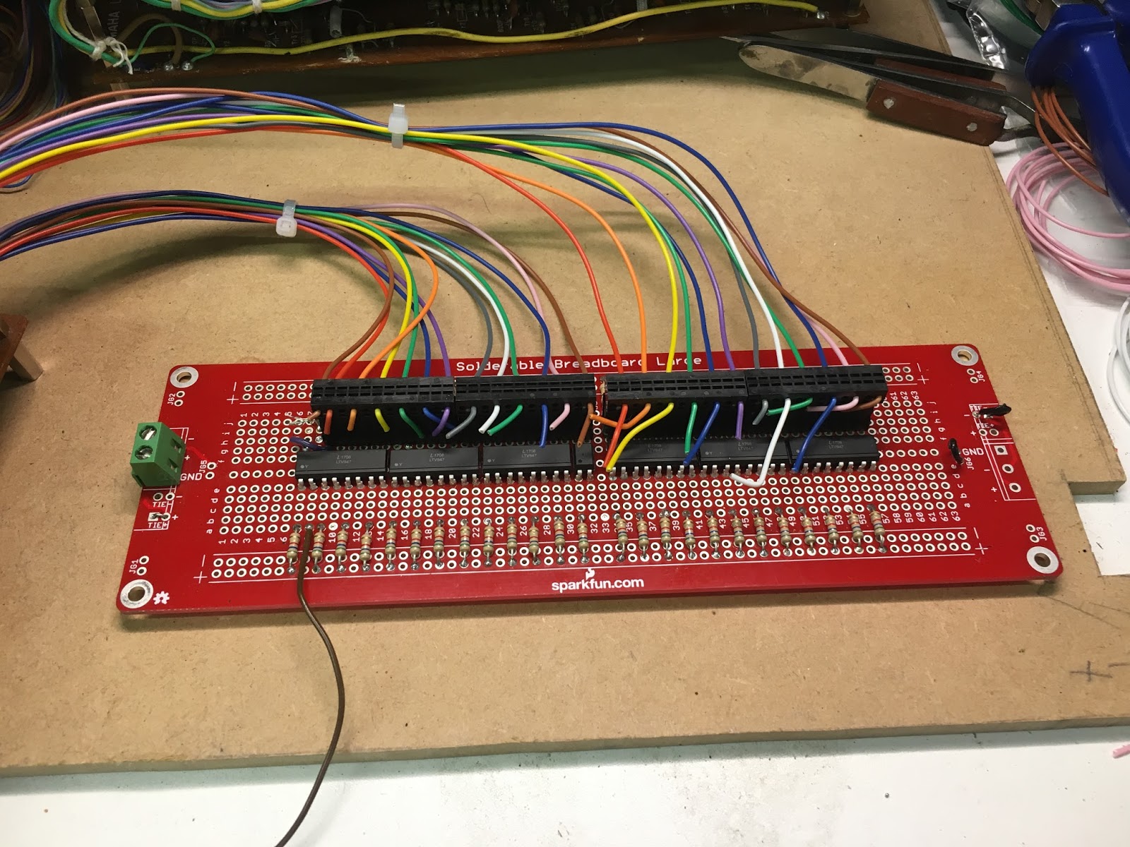
The first problem I encountered was that my lovely connectors were too big for the wires on the K-boards. I had to go and order another batch of wires and then add new wires from the K boards to the connectors. This took a lot longer than I was hoping but I had no real choice.

Lotsa, lotsa wires.
K1 and K2 boards wired to connectors on the first interface board.


Much soldering and wiring later I had the first board (err) wired up and - somewhat to my surprise - all working perfectly.


The first interface board wired up to the MIDI decoder

MIDI IN


I ploughed on to the second interface and suddenly I had a MIDI controlled SS-30!


MIDI Interface almost complete


 So, I'm almost there. I have to sort out the power to the decoder now though. So far it's been run of a bench PSU and I hope to get it running off the SS-30 supply. Thats' another post though.

I meant to get a recording of the whole thing being played, but it's not done yet so I'll end this post on that tantalising prospect.


'Opto-mum' Currents?

This post is a bit behind events now (more on that to come) but here it is anyway.

'Opto-mum' Currents?

Before I launch into building the coupling boards that will interface the MIDI decoder to the key switches I need to actually do a bit a electronics design with equations and everything! The first task is to ensure that opto-couplers have enough current on the input to make sure there is enough current on the output. The input is an LED, so if the current is too low the light emitted by the diode will not be sufficient to turn on the photo transistor fully. In that case the voltage drop across the phototransistor will be too low and the switch will only be partially on. It might be enough to hear something, but I don't want a quiet SS30.
The second task is to limit the current to each input so that the cumulative load of the switches is not drawing hundreds of milliamperes. With 49 keys the potential is there to simultaneously draw more current than the power-supply can handle and blow the fuse. The power rails on the SS30 are rated up to 500mA and if possible I want to use the +15V supply for the MTP8 and the couplers.
Therefore I need to find the optimum current for each optocoupler input - not too low and not too high.

MIDI Decoder 

The MTP8 draws around 15mA for it's own logic etc.
The maximum current per output in the MTP8 is 500mA. But, each group of 8 outputs is limited to 2A which translates to 250mA per output with a possible maximum for 49 keys of 12.25A(!). All that means is it can comformatbly handle large currents. But I want as low a current as possible.

K Boards

The K boards key-switch 'input' is held at -7V through a 3.3K resistor. That means we should getting around 2mA through each switch.


KS-M-C3 is what goes to the key to be switched to ground

The measured value I got from one I picked at random was over that so my calculation must be mistaken somewhere.


And, hey, look! That's my new multimeter.

2.37mA means that the voltage is actually higher. I usually measure around 7.7V which results in a current of 2.33mA, which is much closer. In any case I measured approximately 2.4mA so that is my target output current.


Opto-Coupler Characteristics

Transistor outout optocouplers have many charascteristics but the main one I'm interested in the CTR. The Current Transfer Ratio - expressed as a percentage - simply decribes the relationship between the input current to the LED and the output current. This is essentially the gain of the coupler. All I have to do is make sure that the gain is 100% and they will be no loss through the output, thus mimicing the elecro-mechanical switch I'm replacing. But, what if the gain is a lot greater than unity? Does that mean that somehow the current through the going to be higher? Err, no. The current cannot be any higher than the 2.4mA I measured, but you can have a CTR above 100% because the input current can be lower than the output. This is the kind of coupler I need because if I had to have 2.4mA available for every input I would need 118mA to cover the entire 49 keys. I want to target 50mA or 1mA per switch. 


When I set up the single octave test I had just grabbed some opto's from Maplins - Vishay IL74s - without looking too closely at this CTR characteristic.
The IL74 - data sheet here - has a quoted typical CTR of 35% for 16mA. But the datasheet also shows that it ranges above 100% when the current is greater than 20mA. To be honest I worked through the datasheet and it was a very long and boring process which required this guide on how the CTR graphs should be interpreted. Vishay take the long road and I'm not interersted in that here, so instead here's the shortcut.
I was using 1K current limiting resisistors with a 15Vsupply in that test. The input current (If) was then measured as 13.34mA (the voltage drop across the resistor being 13.34V). A lot higher than I was looking for but that comfortably switched the keys on. The effective CTR in that case was then (Ic/If) 2.34/13.34 x100 =  17.54. Experimenting with other resistors and supply voltages I managed to get good results with 9V through 1K2. This was 2.59mA If and 2.08mA Ic giving 80% CTR. However I couldn't do any better and I want to get the input current down to more like 1mA. This would require a CTR of  234%.


The LiteOn LTV-847 has minimum CTR from 50% (for 5V/5mA) but a maximum of 600%, which seems much better than the Vishay part, and they are quite cheap, so I ordered these.
Avoiding the datasheet again I worked through a series of resistsors from 1K to 10K and measured the input current and output voltage drop. I was looking for the point where the input current is low but not so low that the output current is throttled and the voltage drop across the output collector emitter is rising.


Since taking these measure I seem to have lost the info what the supply voltage was. Was I used 9V or 12V or what? Ah well. When I go the 6K8 resistors I decided they were too high and although the voltgae drop shoudl have been relatively little i t was much higher. May be I changed the input voltage? In any caseI decided to change to 5K6 and as I had enough 'in stock' I used those instead. It was time to start building!