I'm currently working on completion of all the modifications and wiring up all the connectors and controls I left incomplete back in 2018. I have a couple of posts I'm drafting about all that, but I had to break off to deal with the Pitch CV input seperately. It another post with a lot of detail!
Back in 2018, I tested this new feature and wrote about it in this post: Pitch CV Input Test
I don't recall any particuar issues with this test. It took a little bit of adjustment of the Eurorack level voltage I was using, but overall it seemed to work as expected for a pitch LFO (AKA vibrat
o) input.
Now though, I have taken things up a notch!
Tuning In-troduction
On the SS-30, the instrument is 'tuned' when the Pitch Control is pointing to the marker at around at around half past10. The Detune (DT) is also in tune with the Pitch Control (PC) setting in this position.

On my machine, it's bit more like 11 o'clock and half past ten.

Now let's get into how this works inside.
The destination of the PC and DT settings is the two Master Oscillators, but also there's Vibrato to consider and things are little more convoluted than that sounds.
Overview
This is the overview.

It does not help that there's a typo in this. The input to the G4 Master Osc' is actually more like this.

There are three inputs to set the tuning - PC, DT and the Vibrato LFO. These are mixed to create the two outputs for the Master Oscillators.
Voltage Mixing
Here's the Voltage Mixing schematic with the output of the Vibrato also shown. The Vibrato Depth control is not shown here.

The PC and DT are voltage dividers setting an output between -15V and +15V .
The Vibrato is set between 0V and 1.7Vpp by the Vibrato Depth control.
Each mixer is an inverting summing amplifier.
The top mixer (V1) has three inputs
Reference voltage - +15V
Pitch Control voltage -15V to +15V
Vibrato LFO voltage 0 - 1.7Vpp
The bottom mixer (V2) has four inputs
Reference voltage - +15V
Pitch Control voltage -15V to +15V
Detune control voltage -15V to +15V
Vibrato LFO voltage 0 - 1.7Vpp
We can easily calculate the outputs, based on the input voltages, except for the LFO whose voltage is affected by the circuit in a way that's not obvious from the schematic. Suffice to say, when the Depth setting is fully on, it's input to the mixer is not 1.7Vpp.
The voltages are calculated using the usual equation
-Rf x (Vin/Rin)
Hence the refernece volatge contribution to the output is
-10,000 x (15/15000) = -10V
And if the PC voltage is +5V, the contribution from that is
-10,000 X (5/82,000) = -0.61V
And so the V1 mixer output voltage with no Vibrato is -10.6V
Assuming the DT voltage is also +5V the V2 output voltage is -11.2V
Attempting to match up these numbers with the Service Manual is not easy. There's no indication of what the PC and DT volatges should be to obtain these traces, but the -12V to -13V level from V1 mixer would indcate a -1.5V conttribution from PC.
Switching to the V2 mixer, where PC and DT are summed with the reference voltage, the DC component is -10.5V, therefore DT must be +1V - (-10) -1.5 = -11.5.
Back to the LFO, the actual input AC voltage can be derived from the Service Manual diagrams, again assuming the 1Vpp differential output.
To obtain +0.5V the equation is -10,000 x (Vlfo/1,200) = 0.5 Or 0.5/-10,000 = -5e-5 = Vlfo/1,200 Or Vlfo = -5e-5x10,000 = -60mV, which is a lot less than 1.7Vpp.
The issue here is the input impedance of the Rin resistor for the LFO. 1.2K is not that high and the virtual earth of the op-amp input is drawing a lot of current and that is causing a drop in the voltage.
Meanwhile, back in the real world I took some measurements on my SS-30.
Taking a reading off from "C" pin on Master OSC ICs on the G2 board I tuned the PC to the marker and then adjusted slightly to obtain C4 - 261.63 Hz.

Then, I measured voltages and the frequencies with different settings.
Tuned
G2 - IC1 - 261.63Hz
Pitch Control Voltage - +4.83V
G4-PC - -11.4V
Fully clockwise
G2 - IC1 - 264.5 Hz
Pitch Control Voltage - -15V
G4-PC - -9.48V
Anti-clockwise
G2 - IC1 - 258.8 Hz
Pitch Control Voltage - +15V
G4-PC - -13.24V
IC2
Detune - Tuned - 261.63 (??V)
Fully clockwise 265.7 Hz
Anticlockwise 259.8 Hz
As you can see, the values for the PC output from V1 mixer indicates that the Service Manual can't be quite right. Only by adjusting PC fully anti-clockwise is -12.5 obtained. However this discrepancy is not a problem. I'm just observing that there is not shorcut to understanding this circuitry.
Master Clock Oscillator
Going deeper into the SS-30, the control volatge to Master Oscillators is a bit more wide-ranging than it first seems. Now that is interesting.
Using the data from above I can say that the range of tuning on the SS-30 is:
Pitch +/-19cents
In Hz, I measured +2.87Hz and -2.83Hz
The range is small, but we knew that. Less than a quater note.
The notable thing is that the tuned postion of the PC is in dead centre of the range of pitch control, but is physically one third of the controls' range in. To put it another way, the PC voltage ranges over 30V and is centred around 10V from the top of that range.
I might have expected to get a ange that was even/symmetrical about the centre of the control, but instead it's offset.
That the Master Oscillator control voltage in not following a linear scaling is not a total shock. Yamaha and Korg used the hertz per volt scheme for intefacing mono synths anyway, but so called linear scaling, 1 volt per octave, is not a natural feature of electronic oscillators.

The output of the voltage mixer I measured was increased 1.7V from minumum to tuned and then another 2.06V to maximum.
The total range for the PC into the Master Oscillator is 30V into 3.76V.
The calculated value is 10,000 x 30/83,000 = 3.6V
I then applied a DC volatge through the Vibrato LFO input and found the following limits for the oscillator.
Minimum -14V
Median -3.7 (tuned to C#4)
Maximum -1V
This gave an output on the G2 IC1 'C' pin of
Minimum 257.9 Hz - C4 -25 cents
Median 277.2Hz - C#4
Maximum 294 Hz - D4 +2 cents
Hey! Now, that's more interesting than +/-19 cents!
This wasn't giving me the whole picture though, so I took a measurement of the frequency at 1 volt intervals.
-2V 283
-3.1 279.3
-4 276.5
-5 274
-6 271.3
-7 269.1
-8 267.1
-9 265.3
-10 263.6
-11 262
-12 260.6
-13 259.1
Including the other meaurements, I plotted a graph.

The red markers are C4, C#4 and D4.
The yellow markers are the lower and upper range of the PC.
This is clearly not a linear scale of tuning. In the volts per octave system the difference in voltage between notes (not frequency) is always the same. In the usual 1V/Octave standard this is 0,08333V per note.
In the data I have gathered there is a difference of 7.7V between C4 and C#4 and a difference of 2.7V between C#4 and D4.
Is this instead the Hz to Volts exponential system? Yamaha and Korg used this system for pitch control voltages instead of 1V/Oct.
In Hz/V, the increase in frequency is proportional to the voltage. A double of frequency (an octave) would need a double in voltage. Similarly, any multiplication of voltage leads to a identical multiplication of frequency.
In my example C4 = 261.3Hz/-11.4V and C#4 = 277.2Hz/-3.7V.
The multiplier for the frequency here is 277.2/261.3 = 1.060849598163031
Whereas the voltage actually increases by a factor of 3.08 (inverted).
Applying the same multiplication to voltage as frequency (inverted because the voltage is negative) gives -10.74V
In the region over which the PC works we can say that increasing +10V (2.08V at the osc input) from the tuned position decreased the pitch by 19cents or 2.5Hz. And decreasing -20V (-1.84V) from tuned gave an increase of 19cents or 3.2Hz.
1.84/2.08 = 0.9
2.5/3.2 = 0.78125
1.84/2.08 = 0.9
2.5/3.2 = 0.78125
Which means that this isn’t exponential either.
At this point in the investigation I was strating to wonder if I could find a way to manage the control voltage. First though we need to examine the Vibrato LFO.
Vibrato
Refering back to the schematic (above) the Vibrato LFO is a bipolar, triangular waveform which is AC coupled to the Pitch Voltage Mixer. I measured the Vibrato LFO and found it was more like 2.3Vpp than 1.77V. I think that I tweaked this higher - using the timmer at the output - to get a more intense Vibrato. This does seem to have the effect of making the Vibrato leak through even when the Depth control is a minimum though.Note that I measured this by disconnecting the LFO from the Pitch Voltage Mixer as there is a signficant voltage drop due to the low impedance of the input to the mixer.
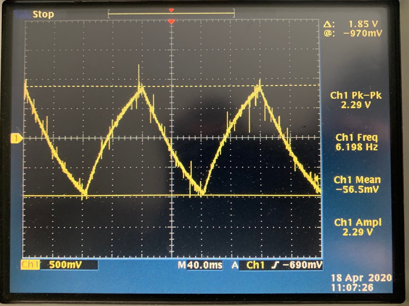
Once the Depth is turned up to full, the LFO output is dragged down to 250mV, but with a lot of peaking and noise around 2.3Vpp still.

That's the input to the mixer, but what about the output?

Wait, what? The amplitude of that LFO signal is 2.2V? It appears the LFO is passed through at unity gain. But, that cannot be correct, right? Well, yes, the voltage at the input is actually 250 mVpp so that's about right.
Let's run the numbers again.
Vo = Rf x (Vi/Ri)
Vo = 2.2V
Rf = 10,000
Ri = 1,200
Vi/Ri = Vo/Rf
Vi = (Ri x Vo)/Rf = (1,200 x 2.2V)/10,000 = 0.264V
Which is about the same as the measured input, so why does that input end up so much lower than the output of the LFO actually is? Even using another source of LFO the voltage is lower and disconnecting the Depth control too gives the same result.
Impediment to progress
I have to admit I got a little stuck here until I recalled how input impedance and output impedance relate and effect the voltage and curent of the signal.
In general, a high impedance input is a good thing because it limits the amount of current (and therefore power) drawn from the output. Then the design of the output stage can be simplified because the demand on it is low. To make this work the output impedance must be lower than the 'high' input impedance. Othewise the power drawn from the oputput will be too high.
Too high in this case means that the 'low' impedance output cannot deliver that power and something had to give. With less impedance to the current flow, that will increase and the only way for the power to be maintained whilst increasing the current is to drop the voltage.
This voltage drop is exactly what is happening in the LFO input. It appears that Yamaha's designers decided that that instead of using a lower level of signal with a high input impedance they opted to 'show' the relatively high level outout of 1.7Vpp (higher on my adjusted unit) an input impedance of just 1.2K. Note that although this resistor is inline with the high input impedance of the op-amp, the potential on the input is a 'virtual ground' and the 1.2K is the input impedance the input 'sees'. Hence 1.7Vpp is dropped by a factor of around 10 and then multiplied by a factor of 10 by the amplifier.
Unfortunately this creates an non-ideal solution with using his as an input from a control voltage. Eurorack output impedance is between 0 and 1kOhm and expects an input impedance of 100k. That's why my Euro levels are getting dropped too.
Is this a problem?
Eurorack
When I started into this I experimented with the volatge levels inserted to the LFO input to find the useable range. I found that the CV input only has any effect in negative voltages with a maximum Vpp of 1.3/1.4V. |
| Modular LFO - offset and scaled to range between 0V to -1.37V |
The SS-30M responded well to this, but offsetting it back up to centre around 0V it was audible that the positive half of the waveform had no effect on the pitch.
This was puzzling then, but now I can see what was going on.
It's an inverting summing amplier, so all postive volatge are switched to negative and vice versa
The refence tuning adds -10V
The pitch control add -0.6V
The LFO adds around 1-2Vpp (depending on if you adjust the LFO output.)
The usable range was from around +350mV to -1.33V input
PC swings from -13.5 (through -11 ish for tuned ) up to nearly 0V, where is drops out.
The lower range (-350mV/-13.5V) is 257.9HZ
The upper range (1.33V/-0.1V)) 294.6 (approx)
Pitch Control Voltage
- As already shown, pitch control voltage is possible
- 2-semitones of range is available.
- The ideal place to insert the pitch CV is through the Vibrato LFO input to the pitch voltage mixer.
- Using a make-to-break input the LFO can be disconnected
- There is then a clean input with no other voltage
- Pitch and Detune controls will work as normal.
- The Depth Control provides easy access to the input
- The Vibrato LFO input to the mixer is low impedance
- This drops the input voltage
- The gain of the mixer makes up the lost voltage
- The actual control voltage cannot be assumed beforehand and the voltage drop is hard to estimate
- The available CV output power will effect the voltage
- Some buffering may be required.
- The response of the Master Oscillator to the control volatge is not clear
- It isn't linear or exponential
- it will need a bespoke scaling to even out the response.
Working backwards...
- The Vibrato LFO is disconnected when the Pitch CV input is inserted in its place
- The pitch CV comes from the Kenton Pro 2000 MIDI to CV converter Aux output, passed through a fixed attenuator and Eurorack buffered multiple (any buffer will do).
- The Pro-2000 output voltages are set to obtain the maximum range through the attenuator and at the limits of the SS-30M tuning range.
- The MIDI controller for the aux output is set to 2 Breath (see below for why)
- MIDI data to the Kenton comes from my PC via Cubase
- In Cubase
- An MIDI track is set to output tothe Kenton
- An instrument track with MIDICurve VSTi is
- Set to accpet controller 2 data
- Set with a curve for the SS-30M pitch response
- set to output to the MIDI track
- Another MIDI track is set to:
- Output to SS-30M
- Have a Transformer MIDI Insert to convert Pitchbend data to Controller 2
- Send MIDI to MIDICurve
- Accept MIDI Input from a controller keyboard
- A keyboard with pitch wheel has it's MIDI output connected to the PC MIDI in,
Keyboard Controller
Normally, I have been using my beloved old Yamaha PSS-580 because the 49 keys running C-C is an exact match for the SS-330.For this first implementtaion of the pitch control I need something with pitch and mod wheels. I have a few options but nothing exactly right.
Something to think about another time.
The controller is goig to send MIDI notes, Pitchbend and Modulation data
Cubase
Three tracks are needed to handle this. One to take the MIDI input and output MIDI to the SS-30M and Another for the MIDICurve VST and a third to take the output from MIDICurve and the keyboard controller to the Pro-2000.SS-30M MIDI Track
Input: MIDI port from keyboard controllerOutput: SS-30M port is send the note on/off messages
Send: MIDICurveIn for the pitchbend data
MIDI Curve Intrument Track
MIDICurve is a simple VST instrument which takes controller data as the input and changes the value according to the curve. You can set up-to 32 points in the 0-127 ranage and then set up curves between the points to smooth or twist the response.The only issue I have with it, is that it does not accept pitchbend data, so to use a pitch wheel I need to convert to another controller type first.
This is the curve I plotted by measuring the frequency of the SS-30M's top-octave generator output and adjusting the output values from midiCurve till the tuning matched up to the input value.
| Target note | Target frequency (Hz) | Input Value | Output Value |
| C | 261.6 | 0 | 0 |
| C+25c | 265.431 | 16 | 32 |
| C+50c | 269.292 | 32 | 58 |
| C#-25c | 273.209 | 48 | 78 |
| C# | 277.2 | 64 | 92 |
| C#+25c | 281.214 | 80 | 98 |
| C#+50c | 285.305 | 96 | 102 |
| D-25c | 289.455 | 112 | 114 |
| D | 293.6 | 127 | 127 |

Kenton Pro-2000 Track
Input: Set to Any to take data from both the MIDICurve and Modulation data from the keyboard controller.Output: MIDI port for Pro-2000.
Pro 2000
The Pro-2000 can output +/-12.6V on its Auxialry outputs.The limits of this are set by the setttings:
AUX x OUTPUT LEVEL For cntrl Min(-64 to +64, default: 0)-sets the auxiliary output level for when the MIDI Controller Source is at its minimum.
AUX x OUTPUT LEVEL For cntrl Max(-64 to +64, default: 64)-sets the auxiliary output level for when the MIDI Controller Source is at its maximum.
AUX x OUTPUT LEVEL Reset Level(-64 to +64, default: 0)-sets the level that the auxiliary will reset to when a MIDI reset command is received.
I use these settings to align the MIDI values' minimum and maximum (0 and 127) with the voltages needed to obtain the two semitone range. Owing to the inverting input at Pitch Voltage Mixer, the Maximum is set to a negative value, and vide versa.
Output level at Controller Maximum: -51 / -0.918V Pitch : 127 261.1Hz C
Reset level: -31 / -564mVmV Pitch: 64 277 Hz
Output Level at Controller Minimum: +20 / +363.7mV Pitch: 0 294Hz D
The Reset Level of the Pro-2000 is set as close to the middle semitone as possible, but note that this not the middle of the range of value - the acle is not linear, remember.
The important point here is to try and get as much control over the voltage as possible. Therefore setting the maximum and minimum as high as possible is better because it allows for more steps between maxium and minimum and more control. Of course, setting as high as possible is then too high for the input level of the SS-30M, but that's relatively easy to solve...
Attenuator
A simple passive attenaution is all that's needed to divide the Pro-2000 voltage, but using a variable attenuator would mean fine-tuning that as well as the levels in the Pro-2000 and in MIDICurve.Instead I've opted for a special cable with fixed resistors so that I can allows use the exact same voltage divider with no further tuning.

The divider I arrived at is the first one I thought of.
R1 10K / R2 1K
Vout = 1/11 x Vin = 0.0909 x Vin.
Buffer
Although the output of the Pro-2000 has plenty of current for most applications, the low impedance input to the Pitch Voltage Mixer eats up voltage and as I just added another level or output impedance with the attenuator I need another stage to buffer to input.At the moment I'm using the Frap Tools 333, which is overkill in this application, but does the job.
Pitch CV Input
As already mentioned, the 3.5mm jack input breaks the signal from the Vibrato Depth control to the Pitch Voltage Control Mixer and replaces it with the Pitch CV input.Pitch Control
Now the Pitch CV is added to the mixer all that remains is to adjust the PC to a level which optimises the range and is easy to dial in for future use.
This setting is PC to fully clockwise. This is easy to find and works nicely for the input CV.
Conclusion
And there you have it. +/-1 semitone control of the SS-30. Maybe this is how Tomita did it?The voltage control part is fairly easy. The only cleverness needed is the MIDICurve to correct for the strange tracking of the master oscillator over its full range.
Videos demonstrating this to follow!
No comments :
Post a Comment