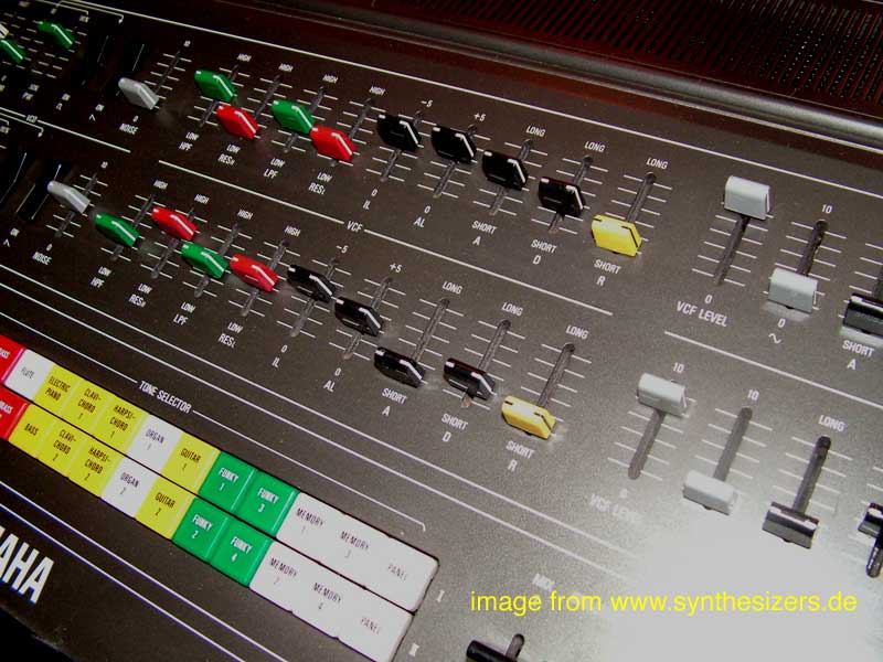
>
YAMAHA
STRINGS
SS-30
RACK-MOUNTED WITH MIDI
MIDI STRINGS

Thursday, July 27, 2017

Viola Woes

Chords


So, here's a short bit of actual chords on the SS30-M.

No Alla Viola - Silenzio

(These heading puns are getting more convoluted by the week. Top marks if you can unpick that one)

Last time I fixed the missing clock to G3. Finally I was done with the SS-30 problems! Or was I? No.

After having missed the fact that I had an issue with G3 I went more carefully through each octave and found another problem. On the bottom octave (K1/G1) there was no output from the Viola.

Tracing this problem took me to a board I've not had any issues with so far - LF.

On LF there are a pair of analogue switch ICs.

4016 Analogue Switches on LF Board


The Old Switcharoo

These 4016 devices control the signals which get selected in and out by the Keyboard Switch control. Either the Cello is selected or the Viola/Violin voices. This is called the KYB. Split Gate.


KBD. Split Gate

In this case 16U from G1 was arriving at the switch gate but not being routed through. I could see that the voltage from the switch was working fine so the problem was really with the IC.

I've ordered the replacement so it should be another easy IC swap when it arrives. The main concern is to make sure no wires break loose whilst the boards are being moved around.

And then I can start on the full MIDI interface. I have a couple of posts in the works about that.

LF Board


The LF board hosts the vibrato, pitch control, sustain control and the oscillators for the Orchestra effect.

I guess the LF board is named Low Frequency because the Vibrato and Orchestra oscillators are essentially LFOs. 

F Board


Wednesday, July 26, 2017

Flippin' Flopped Flip-Flop

There's something about blogging and cafe's isn't there? Well, I am writing this from a cafe in Paris, so this blog now has a certian je ne sais quoi it was lacking before I think. But really, je ne sais quoi. Whilst I'm away from home it's a good time to catch up on progress, of which there has been plenty since the last post.

Last time I was basking in the glow from having got one single note to play. Well I wasn't going to stop there.

Striking a Chord.


I decided to buy a few 4-channel opto-couplers from Maplin's and just see what would happen if I got a whole octave working at once.


Well, this was pretty exciting!


The thrill of playing actual chords from the SS-30on a keyboard for the first time in what must be 20 years was quite something for me. I went to bed late but very happy that night, but there was something bothering me at the back of my mind...

 Feeling Jitttery

In the post before last I mentioned that although the master clock on G3 was back in business I had some concerning waveforms. When I looked at the test points I saw that the waves we jittery. Jitter is a term from digital electronics to describe variation in timing between the signal and a clock, so I'm misusing it here but the effect was that the output from the octave divider IC was not stable. My ears told me everything was fine so I didn't immediately know what to do.

Just before connected the K2 board up for my coupler board test above I ran through each octave to decide which to use. It was then that my ears detected a jittery sounding problem with the top octave from K4. No all the keys but about half had a noise that sounded digital and related to the clocks.  After the triumph of playing a chord I came back to investigate this. Initially I was confused because it was coming and going. Some keys which had the problem seemed okay. Then I noticed that the vibrato was effecting the noise so I turned that off and played with the pitch and detune. Now I could make the problem come and go with the detune. Each tone was effected differently so I surmised that this must be related to the interaction between the two oscillators clocks for each tone and that it was specifically effecting the top octave.


Getting busy with the oscilloscope I soon saw that in fact there was no clock at all on one of the G3 board octave dividers. 
Oh no! could this be a dead YM25400? If it was I was in for some serious heartache. Thankfully tracing the input to that IC showed that the problem was further back. So, the jittery signal I'd seen and heard was because one half of G3 wasn't getting the second oscillator.

Divide and Concur


The problem actually stemmed from the flip-flop divider chip on G3 which divides the 500KHz master clock oscillators from G3 and G4 in half, to 250KHz. The octave dividers provide a 1/4 of the input clock output, as well as the octave division for each note. The dividers on G4 provide a 125KHz clock to G2 and the G3 divider 62.5KHz to G1. Hence the input for G3, which must be half of G4, comes from the flip-flop dividers.

Flip-flop - TC4027BP


The TC4027P dual JK flip-flop IC is thus fed inputs directly from the master clock oscillators of G3 and G4.

Master Clock Oscillators from G3 (top) and G4 (bottom)


I could clearly see that whilst the inputs to both of the two flip-flops was okay, the only output was the one with the G4 clock input.

G4 Master Clock Oscillator input (top) and flip-flop output (bottom)


Even after disconnecting the wire running from the output on one side of G3 to the other there was still no signal to speak of. Reducing the scale showed something was there - all but nothing compared to the other output.


Flip-flop input 2 (top) and output 2 (bottom)


The 4027 was half dead.

The fact that this chip is adjacent to the blown transistor I had just replaced and uses the same -15V supply cannot be a coincidence. 

Flip-Flop Swap-Shop


After being slightly disconcerted that none of the main electronics shops sell these devices anymore (I assumed these parts would be around for ever) I found some at a reasonble price on eBay and they were posted the next day.

A few nights later I setteled into my comfort zone (I must have replaced dozens of DIPs back in my test and service tech days) and replaced the part with alacrity.

If you're not familar with changing DIP ICs the trick is to snip off all the legs before you go near the soldering iron. That is unless you have a pot of solder on the heat nearby, and then you can (after protecting the neigbouring parts and being liberal with your flux) place it pin-side down in the bath and pluck the IC out as soon as the solder has melted.

Faulty TC4027BP with legs snipped off.
 Then it's time to deloder each leg in turn. Doing it this way avoids putting additional strain on the pads as you try and get each one free. Ideally you have through-hole plating so that you can desolder from the top, where you pull the legs through. In the case of the SS30 there is no pad at all on the top side for the ICs so I had to do it in two stages: first on the bottom side I heated the solder on each pad and desoldered with wick (suction is liable to pull the pads of); then I used the iron to push each leg through to the top-side. As there is no solder through the hole they usually fall through without too much trouble.

Top-side of G3 board with IC removed


For most I have to do some more desoldering after pushing the leg through and then turn the board over and heat the leg from the top using tweezers to remove the last obstinate couple. Finally I went back to the bottom-side and used the wick again to remove the remaining solder. The main concern with that is to make sure that the legs of the new chip would slide cleanly through. With plated through-holes this can be a real pain to do cleanly.
 Even though I was careful I still lost a part of one of the pads though. This is typical for a pad with no track, as in this case. Because the pin is linked to the adjacent pin it still held enough to solder though.

Bottom-side of G3 with IC pads cleaned.
The new chip was a very close match to the original Toshiba part.

Old part (left) new part (right)


New part soldered in place


Soon everything was back to normal and the jitter was gone as all clocks were present and correct.


Both outputs from the flip-flops


Friday, July 14, 2017

MIDI Interface - Test #1


I am conscious that this project is taking a long time. As you can see I'm going through another rush of activity whilst the weather is warm and I can sit comfortably in my drafty garage but how long it will last, I don't know. In the last post I said I would pack the boards carefully into the rack enclosure before making a start on the MIDI interface at long last. Well, last night I thought again. Now I have my new bench power-supply I decided I would just check if the j-Omega MTP8 I bought back in (checks blog) 2009 was powering up okay.

I'm pleased to report that when I set-up a 15V supply the MTP8's power LED came on. At this point I couldn' t resist trying a simple test with an LED. And it worked.


The MIDI keyboard I'm using is my trusty old Yamaha (of course) PSS-580. A lovely example of the Portasound breed with a programmable 2-operator FM synth and useful MIDI spec. It says it's a Workstation and it really is. The fact that it's nearer in age to the SS-30 than to now is slightly amazing to me though. It is possible to record sequences on this keyboard too so for testing it will be possible to set up a simple note on, note off for each key which I can play at will. I could do this from my phone or iPad with a MIDI interface too. I might re-think and do that but for now I like having a keyboard and I can easily use it for a tuning reference.

Here's a fun demo I found on YouTube of some of the more extreme possibilities of the synth section.


Handily, the keyboard is exactly the same size as the SS-30 - 49 keys from C1->C5 - so it's ideal for this project. And although I still have a soft spot for this keyboard  - it was my first ever synth - it's not in use in my studio these days. I have a Volca FM performing FM duties, so it's not really required.
Something else I will need to do is check the range of the keys used by the MTP8. I connected output number 32 (of 64) and that mapped to G3. If output 1 was C1. C2 would be on 13 and C3 on 25, C4 on 37 and C5 on 49. G3 would then be on 32 so it is mapped exactly as I would have wanted it to. Great!


With the MTP8 working and the SS-30 ready and working I still had time to take the obvious next step -  try to control the SS-30 from MIDI! At long last.

First though I had to find something to handle the switching. As you may remember from this post, on how to switch the -7V keys to ground, there are a few options but the obvious choice is some sort of opto-coupler/opto-isolator. I thought I must have one somewhere and remembered that I have a CNY17 chip. Originally this was used for a failed attempt at a DIY MIDI CV converter. And then it was stolen for a Gameboy MIDI interface. For MIDI it's always recommended to use an opto-isolator and on the MTP8 there's a similar chip for the same purpose. The CNY17 is a passive component of the type I expect to use so I de-soldered it from the GB interface and with a bit of wiring and a couple of resistors on the bread board I could switch the LED on/off through the opto-coupler.

It was the moment of truth. I knew it should work, but could I play one note of the SS-30 via MIDI? Yes, of course  :-)


So there you have it. All I need to do now is make another 48 similar circuits and it's job done!


Thursday, July 13, 2017

Jitter Bug

Fix the jitter bug...!

Well, that's a relief! Last night I fitted a new transistor on G3 and the clock came back to life with a far more healthy looking waveform.

Tr1 Replacement on G3 - A bit wonky as I'm trying to be careful handling these boards to avoid breaking more wires.

 To be frank I'm still not totally happy with it though. I need to spend a bit more time measuring and checking because it still seems a bit, jittery... Not as bad as before but on the scope it's not as stable as the clock on G4.

I've Got The Bench Power

Before trying the transistor I thought I would have another go with a bench power-supply. But this time it was a linear supply, not the switch-mode one I borrowed. Ah, yes, this one is mine! I decided I needed a new toy for when I start work on the  MIDI interface so I bought cheapest one Farnell offered - a Tenma - and it's rather good for fifty notes. It'll appear in a later post no doubt.

Transistor Saviour


Initially I was a bit worried that I couldn't find a replacement for the 2AS509 transistor. I could find expensive ones or cheap ones in the states that would be expensive to ship over but nothing in the UK. Eventually I noticed that BC636 were close match and were cheaply available at Farnell. I bought a few just in case, as there we so cheap.


Back in the S.S.3.0

In any case, it works with the new part fitted and I plugged the output back into my mixer and had a listen - More noise! Oh, but this time I know what to look for. Sure enough a ground wire had snapped off G3. A quick fix and I was finally listening to the SS-30, as it should sound. Hurray!


To celebrate I decided to create a short video of me fiddling with the temporary front panel. Not the most exciting thing you'll watch today I would imagine but it's nice for me to have a record of these things.


You will notice that some of the pots are a bit noisy and sometimes when I switch things in it gets quieter, but overall things are working.

After a few more checks I should now be able to put everything back together in the rack case and after verifying it still works turn to the MIDI interface. The idea is to keep all the SS-30 boards inside the case, have the front-panel easily accessible and then just have the switch PCBs available to connect up with the interface. 


Tuesday, July 11, 2017

Panel Design Re-think & Yamaha's Design Language

Panel Games


I've been thinking about the front-panel and a few ideas have crystallised
  • Don't use the original parts. 
    • I want to use faders/pots for many of the controls.
    • Many of the switches are a bit damaged 
      • and twisting the contacts back into shape is unsatisfactory
    • The huge tablet switches are a bit difficult to accommodate 
    • Brown
      • From an aesthetic point of view brown is difficult 
      • I did envisage having a wooden front-panel at one point!
      • Brown tho?
    • The layout is fixed and limits options when adding other features etc.
    • I have identified some possible modifications which the old parts don't allow for
      • e.g. swapping a switch for a slider. 
  • Base a new design on the look of the CS and SK ranges. 
    • Black with white text
    • CS80-CS5 range
    • SK combos
    • EM Mixers
    • Same era as SS30
    • What a real SS30M would have looked like
  • Use the new Schaeffer UV printing option
    • Means fonts can match exactly
    • Much cheaper than engraving
    • easier to mock-up
    • almost as good as a screen print(?)

The Past Inside The Present

The idea then, is to make a front panel that looks just like something Yamaha would have made circa 1982/83 when MIDI was first introduced, but somehow still from 1977 or earlier, because by '83 the string ensemble idea was archaic. This is only recently more easy to achievable thanks to UV printing. Previously, I had looked closely at engraving, transfers and screen printing - which would have been the ultimate. Now, UV printing means Schaeffer (and Front Panel Express) can offer full colour images in any design for a very reasonable price. This means I am only limited by my imagination and my dream of having something that looks not only professional and pleasant to use but also ersatz Yamaha, circa late 1970s.

http://brochures.yokochou.com/en_index.html#YAMAHA_EFF

MIDI started to appear in 1983 and that was the year Yamaha unleashed FM on the world (GS1/GS2 excepted) and it's not that era that I want at all. The year before was the last of the analogue's, but apart from the SY20 the design language had already started to move on. 1981 say the mighty CS70 and SK15. 1980 was all about the SKs with, SK20, SK30 and SK50D. 1979 saw the first of the SKs with SK10 and the last of the CS beasts with CS-15D, CS20M and CS40M. In 1978 they kept it simple with the all black and no wood CS-5 and CS-15. 1977 was the year of the SS-30 and Yamaha was very busy with the CS range  - 50/60/70 - and CS range - 10/30/30L - both kicked off. Finally the SY1 started it all in '74 followed by the expanded SY2 in '75 along with the jaw-dropping GX1.

Meanwhile Yamaha were putting out mixers with similar in-house styling. There we desks and then some cabinet, PA mixers and then rack mixers. Some of these share the same knobs, fonts etc as the synths.
Yamaha's other rack gear was generally for PA systems. The design and 'look' is quite different to the synth and mixer ranges. There are the analogue delays E1050 and E1010 from 1989 but still not very useful as a reference unfortunately. 

I want to plunder this entire period to some degree, so let's look at all of it - or just jump to the summary at the end if you prefer.

CS Polysynth Range - 1977

CS80 CS60 CS50


Fonts

These synths have a gun-metal grey finish with white Univers Condensed


Knobs

 The CS50/60/80 knobs are the same as the SS30 - but in black. These would be the closest match but obtaining them is going to be a problem I think. I have seen nothing even close available from modern suppliers.


Switches

There are a variety of different switches used, including the same tablet rockets as on the SS30.
The presets on the CS 50 and 60 are extra chunky tablets with lips on the front. Proper organ style.

Some are smaller rocker type switches and something similar should be possible to source still but the dimensions and finish will probably not be.

The push type might still be available but I'm not currently thinking I will need anything similar.

And there are some are a sort of lever type 


https://www.axesrus.co.uk/Electroswitch-CRL-Lever-Switches-p/crl3-5.htm

These lever types take the same kind of slider caps as seen below.


Sliders 


https://www.sequencer.de/pix/yamaha/cs80panel.jpg

http://medias.audiofanzine.com/images/normal/yamaha-cs80-173158.jpg


CS Mono-Synth Range - 1977-78

CS5 CS10 CS15 CS30

For the range of CS mono-synths a more 'functional' or industrial aesthetic was adopted to compliment the cheaper price. Wood was eschewed in place of the plastic end cheeks and the look is similar to the Korg MS range.

CS30

Fonts

The legends are Univers, like the CS80/60/50.

Knobs

These look quite chunky and robust compared to the CS range ones. They look almost military spec. Note the 'U' shaped knurls. In the CS30 parts list these are 301000 CB810130
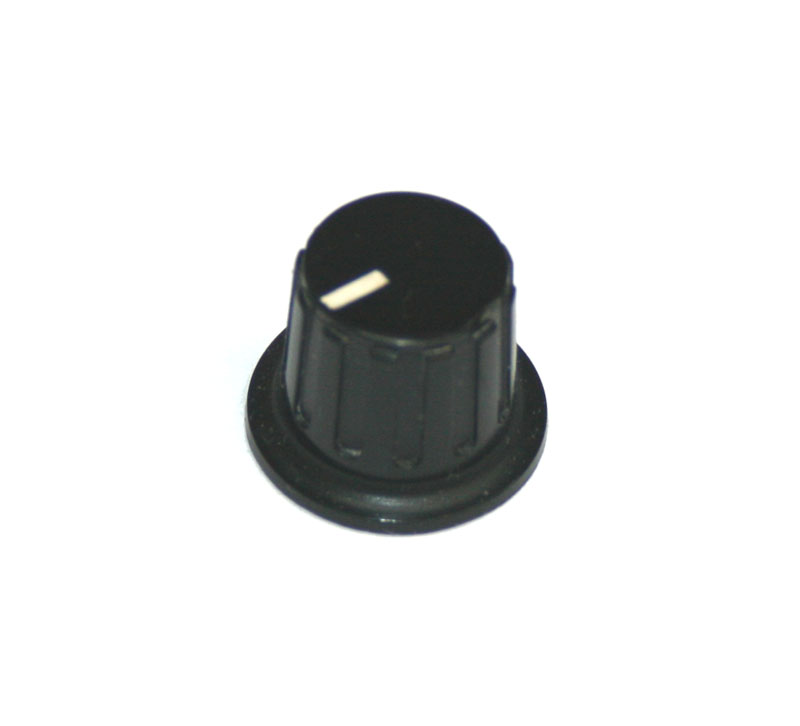
Syntaur

Slider Knobs

Theses CS synths have the same slider caps in the player control section as their poly forebears, but in plain b/w. These are part number 301000 CB811280.


CS15
The CS15 and 30 envelope section uses a smaller slider cap. Part number CB811290.
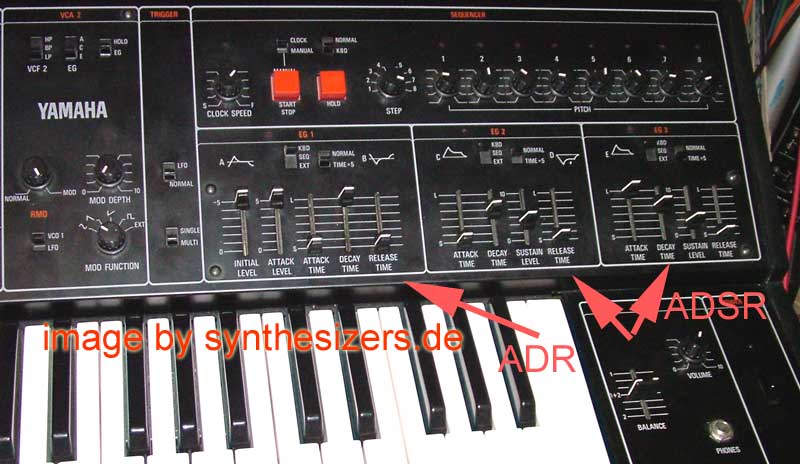


Switches

There are some fat red push buttons on the CS30 but for the most part it's bog standard slide switches all the way. The main difference is that they have natty caps on them so they are protected from dust and other unwanted crud falling to them and the sit flush under the panel. They are stand out prouder from the panel so they are so fiddly. I've looked around for these caps but I haven't seen anything similar.


CS & SK Range - 1979-81

CS70 CS20 CS15D SK10 SK20 SK30 SK50D & SY 20 - 1982


Fonts

The 'hero' font is URW Corporate


The legends seem to be Helvetica


Knobs

These seem to vary a bit but basically they are the same style as the CS mono-synths.


The CS40M and CS70 knobs have a fairly standard caps. The knobs themselves are a slightly less common.
They seem the same as the earlier. 
CB812140 ivory
CB812130 yellow

CS40 - 1979


CS 40 parts list 

SY20 - 1982


SK knobs


Switches

For the push buttons these synths use a variety of common designs from the era, some with a LED integrated. I guess these are momentary switches which don't latch 'on' but send a pulse to the computer to make settings. The LED is then driven by the computer as or electronic latch.

There are some other chunky style push buttons used but there are of no interest to me as I said before.

Slide switches are used as on CS mono-synths with the nice covers again. These covers don't have a separate part number so the issue is.

The SK10 is using tablet rockers.

Sliders

 The CS40M, CS15D and SK10 sliders are the similar to the CS80/60/50 ones but have the special tan/sandy in-fill colour. They also seem to be a matt finish rather than the silky smooth finish on the earlier CS polysynths. 

CS40M
SK10


The sliders on the CS70M, SK50D, SK15, SK20, SY20 are a curious, rectangular design with coloured caps. I have seen nothing like these anywhere before. Also, I'm not keen on the look of them/

Add caption

Mixers 

Yamaha produced a plethora of mixers in the era I'm interested in and I have tried to list them below with the years they appeared on the market. 

EM for Ensemble Mixer. With power amps for speakers and onboard FX - For practice and small stage set-ups
PM for Profeessional Mixer. For sound reinforcement duties  - i.e. live mixing.

Cabinets

These cabinet style units in sturdy Tolex covered wood with metal corners. Clearly intended for live use these mixers provide enough power for speakers. They also sometimes included  built-in effects! The EM89 and 95 had analogue delays (echo) and the EM120 has a spring reverb. I'm tempted to build something based on these as a companion to the SS30M.Or maybe even buy one of these old things and reuse the parts. They still command a reasonable price though so it would be a serious investment. 


EM-120 - 1977
EM-85 - 1980
EM-95 - ?


EM85 1980
EM-120

Desks 

 This post is already too long so let's keep it short on desks.

Ensemble Mixers

EM-80 - 1977
EM-90
EM-100 - 1977
EM-100 II
EM -150 - 1977
EM-150 II
EM300

Sound Reinforcement Profesional Mixers

PM-210 -1977
PM-430 - 1977
PM700 - 1977
PM1000-16 - 1977


EM-80


Rack  - Sound Reinforcement Mixers

These are the closest thing to an SS-30M in a rack  that I can find.

PM-170 - 1978 - Unbalanced Phone Jacks
PM-180 - 1978 - Transformer coupled XLR
M406 - - Balanaced MIC inputs

PM-170


Knobs

The knobs are the familiar rugged style

PM-170 Knob

Guitar Units

VM-100

Summary

  • Panels
    • Black or very dark grey, silk finish. 
    • Powder coating, but later mixers were anodised
      • Note: Schaeffer don't offer UV printing on powder coated panels at present.
    • The cut-outs for faders and switches are rounded in the earlier models
      • Need to think about the edge of the cuts too as anything that is visible should not be shiny bare metal.
  • Knobs 
    • Two types of rotary knobs - the SS30/CS80 style and the rest are rugged - both have skirts/nut covers.
    • Fader knobs are either the split marker style or the rectangular capped style - but I don't like the capped ones.
      • These Yamaha fader caps are rare.
  • Switches 
    • Rocker switches are PCB mount with no obvious panel mounting.
      • Switches are smooth and silky. 
    • Slide switches have covers
  • Artwork
    • Rather than use the standard markers on the rotary knobs - like a clock face - Yamaha synths went for line markers that start at an angle and then bend to a horizontal.    
    • Fonts were Univers, then Helvetica and URW Corporate was used for the large logos.
    • Colours went a bit tan and yellow on black instead of plan white at one stage.