>
YAMAHA
STRINGS
SS-30
RACK-MOUNTED WITH MIDI
MIDI STRINGS

Monday, May 04, 2020

Concert Mates (Videos)

Those who have been paying close attention to the long and winding road that is this project may recall that when I (or rather we, actually) bought the SS-30 it was part of a deal that came up in the supposed purchase of a Minimoog. The classified ad was wrong about the Moog. It was a Realistic Concertmate MG-1 by Moog Music. It also didn't mention the SS-30, but that came home too.

In my mind, the pairing of these two instruments has always been clear. The fact that they came as one deal and had evidently both been 'gigged' seems to suggest a back-story together. They belong together.

Here then, are some demonstrations of the two synths working together.

In each case the individual output I added for the Violin section is being fed through the filter of the MG-1. The Orchestra effect and output stage (with vactrol) of the SS-30 are completely bypassed.

Both synths are being triggered from the same MIDI notes.

At the start of this first video I begin by showing the SS-30M played from a keyboard and then switch to a sequence from Cubase and re-patch the output through to MG-1. After that it's fairly self explanatory. But, oh, I also throw in some pitch control.


In this second video, I'm playing an arpeggio from my Keystep. There's a bit more pitch control too.


The third and final video is again the SS-30M through the MG-1 all driven by the Keystep, but this time it's a sequence.


Pitched battle


I'm currently working on completion of all the modifications and wiring up all the connectors and controls I left incomplete back in 2018. I have a couple of posts I'm drafting about all that, but I had to break off to deal with the Pitch CV input seperately. It another post with a lot of detail!

Back in 2018, I tested this new feature and wrote about it in this post: Pitch CV Input Test

I don't recall any particuar issues with this test. It took a little bit of adjustment of the Eurorack level voltage I was using, but overall it seemed to work as expected for a pitch LFO (AKA vibrat
o) input.
Now though, I have taken things up a notch!

Tuning In-troduction


On the SS-30, the instrument is 'tuned' when the Pitch Control is pointing to the marker at around at around half past10. The Detune (DT) is also in tune with the Pitch Control (PC) setting in this position.


 On my machine, it's bit more like 11 o'clock and half past ten.


Now let's get into how this works inside.

The destination of the PC and DT settings is the two Master Oscillators, but also there's Vibrato to consider and things are little more convoluted than that sounds.

Overview


This is the overview.


It does not help that there's a typo in this. The input to the G4 Master Osc' is actually more like this.


There are three inputs to set the tuning - PC, DT and the Vibrato LFO. These are mixed to create the two outputs for the Master Oscillators.

Voltage Mixing


Here's the Voltage Mixing schematic with the output of the Vibrato also shown. The Vibrato Depth control is not shown here.

As you can see, there are two identical voltage mixers - the op-amps are NJM4558s.
The PC and DT are voltage dividers setting an output between -15V and +15V .
The Vibrato is set between 0V and 1.7Vpp by the Vibrato Depth control.

Each mixer is an inverting summing amplifier.

The top mixer (V1) has three inputs
Reference voltage - +15V
Pitch Control voltage -15V to +15V
Vibrato LFO voltage 0 - 1.7Vpp

The bottom mixer (V2) has four inputs
Reference voltage - +15V
Pitch Control voltage -15V to +15V
Detune control voltage -15V to +15V
Vibrato LFO voltage 0 - 1.7Vpp

We can easily calculate the outputs, based on the input voltages, except for the LFO whose voltage is affected by the circuit in a way that's not obvious from the schematic. Suffice to say,  when the Depth setting is fully on, it's input to the mixer is not 1.7Vpp.

The voltages are calculated using the usual equation
-Rf x (Vin/Rin)
Hence the refernece volatge contribution to the output is
-10,000 x (15/15000) = -10V
And if the PC voltage is +5V, the contribution from that is
-10,000 X (5/82,000) = -0.61V

And so the V1 mixer output voltage with no Vibrato is -10.6V

Assuming the DT voltage is also +5V the V2 output voltage is -11.2V


Attempting to match up these numbers with the Service Manual is not easy. There's no indication of what the PC and DT volatges should be to obtain these traces, but the -12V to -13V level from V1 mixer would indcate a -1.5V conttribution from PC.
Switching to the V2 mixer, where PC and DT are summed with the reference voltage, the DC component is -10.5V, therefore DT must be +1V  -  (-10) -1.5 = -11.5.

Back to the LFO, the actual input AC voltage can be derived from the Service Manual diagrams, again assuming the 1Vpp differential output.
To obtain +0.5V the equation is -10,000 x (Vlfo/1,200) = 0.5 Or 0.5/-10,000 = -5e-5 = Vlfo/1,200 Or Vlfo = -5e-5x10,000 = -60mV, which is a lot less than 1.7Vpp.

The issue here is the input impedance of the Rin resistor for the LFO. 1.2K is not that high and the virtual earth of the op-amp input is drawing a lot of current and that is causing a drop in the voltage.


Meanwhile, back in the real world I took some measurements on my SS-30.

Taking a reading off from "C" pin on Master OSC ICs on the G2 board I tuned the PC to the marker and then adjusted slightly to obtain  C4 - 261.63 Hz.


Then, I measured voltages and the frequencies with different settings.

Tuned
G2 - IC1 - 261.63Hz
Pitch Control Voltage - +4.83V
G4-PC - -11.4V

Fully clockwise
G2 - IC1 - 264.5 Hz
Pitch Control Voltage - -15V
G4-PC -  -9.48V

Anti-clockwise
G2 - IC1 - 258.8 Hz
Pitch Control Voltage - +15V
G4-PC - -13.24V

IC2
Detune - Tuned - 261.63 (??V)
Fully clockwise  265.7 Hz
Anticlockwise  259.8 Hz


As you can see, the values for the PC output from V1 mixer indicates that the Service Manual can't be quite right. Only by adjusting PC fully anti-clockwise is -12.5 obtained. However this discrepancy is not a problem. I'm just observing that there is not shorcut to understanding this circuitry.

Master Clock Oscillator 


Going deeper into the SS-30, the control volatge to Master Oscillators  is a bit more wide-ranging than it first seems. Now that is interesting.

Using the data from above I can say that the range of tuning on the SS-30 is:

Pitch +/-19cents

In Hz, I measured +2.87Hz and  -2.83Hz

The range is small, but we knew that. Less than a quater note.
The notable thing is that the tuned postion of the PC is in dead centre of the range of pitch control, but is physically one third of the controls' range in. To put it another way, the PC voltage ranges over 30V and is centred around 10V from the top of that range.
I might have expected to get a ange that was even/symmetrical about the centre of the control, but instead it's offset.

That the Master Oscillator control voltage in not following a linear scaling is not a total shock. Yamaha and Korg used the hertz per volt scheme for intefacing mono synths anyway, but so called linear scaling, 1 volt per octave, is not a natural feature of electronic oscillators.


The output of the voltage mixer I measured was increased 1.7V from minumum to tuned and then another 2.06V to maximum.
The total range for the PC into the Master Oscillator is 30V into 3.76V.
The calculated value is 10,000 x 30/83,000 = 3.6V

I then applied a DC volatge through the Vibrato LFO input and found the following limits for the oscillator.

Minimum  -14V
Median      -3.7 (tuned to C#4)
Maximum -1V

This gave an output on the G2 IC1 'C' pin of
Minimum  257.9 Hz  - C4 -25 cents
Median      277.2Hz   - C#4
Maximum 294 Hz     - D4 +2 cents

Hey! Now, that's more interesting than +/-19 cents!

This wasn't giving me the whole picture though, so I took a measurement of the frequency at 1 volt intervals.


-2V 283
-3.1 279.3
-4 276.5
-5 274
-6 271.3
-7 269.1
-8 267.1
-9 265.3
-10 263.6
-11 262
-12 260.6
-13 259.1

Including the other meaurements, I plotted a graph.


The red markers are C4, C#4 and D4.
The yellow markers are the lower and upper range of the PC.

This is clearly not a linear scale of tuning. In the volts per octave system the difference in voltage between notes (not frequency) is always the same. In the usual 1V/Octave standard this is 0,08333V per note. 
In the data I have gathered there is a difference of 7.7V between C4 and C#4 and a difference of 2.7V between C#4 and D4. 
Is this instead the Hz to Volts exponential system?  Yamaha and Korg used this system for pitch control voltages instead of  1V/Oct. 
In Hz/V, the increase in frequency is proportional to the voltage. A double of frequency (an octave) would need a double in voltage. Similarly, any multiplication of voltage leads to a identical multiplication of frequency. 
In my example C4 = 261.3Hz/-11.4V and C#4 = 277.2Hz/-3.7V. 
The multiplier for the frequency here is 277.2/261.3 = 1.060849598163031
Whereas the voltage actually increases by a factor of 3.08 (inverted). 
Applying the same multiplication to voltage as frequency (inverted because the voltage is negative) gives -10.74V 
In the region over which the PC works we can say that increasing +10V (2.08V at the osc input) from the tuned position decreased the pitch by 19cents or 2.5Hz. And decreasing -20V (-1.84V)  from tuned gave an increase of 19cents or 3.2Hz.
1.84/2.08 = 0.9
2.5/3.2 = 0.78125

Which means that this isn’t exponential either.

At this point in the investigation I was strating to wonder if I could find a way to manage the control voltage. First though we need to examine the Vibrato LFO.

Vibrato

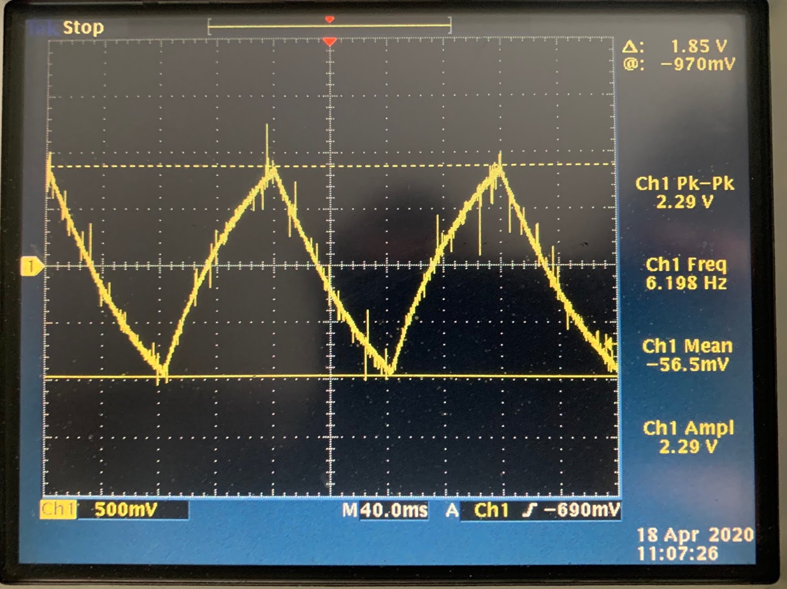
Refering back to the schematic (above) the Vibrato LFO is a bipolar, triangular waveform which is AC coupled to the Pitch Voltage Mixer. I measured the Vibrato LFO and found it was more like 2.3Vpp than 1.77V. I think that I tweaked this higher - using the timmer at the output - to get a more intense Vibrato. This does seem to have the effect of making the Vibrato leak through even when the Depth control is a minimum though. 
Note that I measured this by disconnecting the LFO from the Pitch Voltage Mixer as there is a signficant voltage drop due to the low impedance of the input to the mixer.


Once the Depth is turned up to full, the LFO output is dragged down to 250mV, but with a lot of peaking and noise around 2.3Vpp still.


 That's the input to the mixer, but what about the output?


Wait, what? The amplitude of that LFO signal is 2.2V? It appears the LFO is passed through at unity gain. But, that cannot be correct, right? Well, yes, the voltage at the input is actually 250 mVpp so that's about right.

Let's run the numbers again.
Vo = Rf x (Vi/Ri)
Vo = 2.2V
Rf = 10,000
Ri = 1,200

Vi/Ri = Vo/Rf
Vi = (Ri x Vo)/Rf = (1,200 x 2.2V)/10,000 = 0.264V

Which is about the same as the measured input, so why does that input end up so much lower than the output of the LFO actually is? Even using another source of LFO the voltage is lower and disconnecting the Depth control too gives the same result.

Impediment to progress


I have to admit I got a little stuck here until I recalled how input impedance and output impedance relate and effect the voltage and curent of the signal.

In general, a high impedance input is a good thing because it limits the amount of current (and therefore power) drawn from the output. Then the design of the output stage can be simplified because the demand on it is low. To make this work the output impedance must be lower than the 'high' input impedance. Othewise the power drawn from the oputput will be too high.

Too high in this case means that the 'low' impedance output cannot deliver that power and something had to give. With less impedance to the current flow, that will increase and the only way for the power to be maintained whilst increasing the current is to drop the voltage.

This voltage drop is exactly what is happening in the LFO input. It appears that Yamaha's designers decided that that instead of using a lower level of signal with a high input impedance they opted to 'show' the relatively high level outout of 1.7Vpp (higher on my adjusted unit) an input impedance of just 1.2K. Note that although this resistor is inline with the high input impedance of the op-amp, the potential on the input is a 'virtual ground' and the 1.2K is the input impedance the input 'sees'. Hence 1.7Vpp is dropped by a factor of around 10 and then multiplied by a factor of 10 by the amplifier.

Unfortunately this creates an non-ideal solution with using his as an input from a control voltage. Eurorack output impedance is between 0 and 1kOhm and expects an input impedance of 100k. That's why my Euro levels are getting dropped too. 

Is this a problem?

Eurorack

When I started into this I experimented with the volatge levels inserted to the LFO input to find the useable range. I found  that the CV input only has any effect in negative voltages with a maximum Vpp of 1.3/1.4V.


Modular LFO - offset and scaled to range between 0V to -1.37V
This is a sinewave is from a Roland/Malleko System 540 scaled and offset by a Frap Tools 321.

The SS-30M responded well to this, but offsetting it back up to centre around 0V it was audible that the positive half of the waveform had no effect on the pitch.

This was puzzling then, but now I can see what was going on.

It's an inverting summing amplier, so all postive volatge are switched to negative and vice versa
The refence tuning adds -10V
The pitch control add -0.6V
The LFO adds around 1-2Vpp (depending on if you adjust the LFO output.)

The usable range was from around +350mV to -1.33V input
PC swings from -13.5 (through -11 ish for tuned ) up to nearly 0V, where is drops out.
The lower range (-350mV/-13.5V) is 257.9HZ
The upper range (1.33V/-0.1V)) 294.6 (approx)


Pitch Control Voltage

  • As already shown, pitch control voltage is possible
  • 2-semitones of range is available.
  • The ideal place to insert the pitch CV is through the Vibrato LFO input to the pitch voltage mixer.
    • Using a make-to-break input the LFO can be disconnected 
    • There is then a clean input with no other voltage
    • Pitch and Detune controls will work as normal. 
    • The Depth Control provides easy access to the input 
  • The Vibrato LFO input to the mixer is low impedance
    • This drops the input voltage
    • The gain of the mixer makes up the lost voltage
    • The actual control voltage cannot be assumed beforehand and the voltage drop is hard to estimate
    • The available CV output power will effect the voltage 
    • Some buffering may be required.
  • The response of the Master Oscillator to the control volatge is not clear
    • It isn't linear or exponential
    • it will need a bespoke scaling to even out the response.
And this is what I did to get a control voltage on the pitch of the SS-30M.

Working backwards...
  • The Vibrato LFO is disconnected when the Pitch CV input is inserted in its place
  • The pitch CV comes from the Kenton Pro 2000 MIDI to CV converter Aux output, passed through a fixed attenuator and Eurorack buffered multiple (any buffer will do).
  • The Pro-2000 output voltages are set to obtain the maximum range through the attenuator and at the limits of the SS-30M tuning range.
  • The MIDI controller for the aux output is set to 2 Breath (see below for why)
  • MIDI data to the Kenton comes from my PC via Cubase
  • In Cubase
    • An MIDI track is set to output tothe Kenton
    • An instrument track with MIDICurve VSTi is 
      • Set to accpet controller 2 data 
      • Set with a curve for the SS-30M pitch response
      • set to output to the MIDI track
    • Another MIDI track is set to:
      • Output to SS-30M
      • Have a Transformer MIDI Insert to convert Pitchbend data to Controller 2
      • Send MIDI to MIDICurve
      • Accept MIDI Input from a controller keyboard
  • A keyboard with pitch wheel has it's MIDI output connected to the PC MIDI in,
Got that? Let go forwards and see if it makes more sense.

Keyboard Controller

Normally, I have been using my beloved old Yamaha PSS-580 because the 49 keys running C-C is an exact match for the SS-330.
For this first implementtaion of the pitch control I need something with pitch and mod wheels. I have a few options but nothing exactly right.
Something to think about another time.

The controller is goig to send MIDI notes, Pitchbend and Modulation data

Cubase

Three tracks are needed to handle this. One to take the MIDI input and output MIDI to the SS-30M and  Another for the MIDICurve VST and a third to take the output from MIDICurve and the keyboard controller to the Pro-2000.

SS-30M MIDI Track

Input: MIDI port from keyboard controller
Output: SS-30M port is send the note on/off messages
Send: MIDICurveIn for the pitchbend data

MIDI Curve Intrument Track 

MIDICurve is a simple VST instrument which takes controller data as the input and changes the value according to the curve. You can set up-to 32 points in the 0-127 ranage and then set up curves between the points to smooth or twist the response.
The only issue I have with it, is that it does not accept pitchbend data, so to use a pitch wheel I need to convert to another controller type first.

This is the curve I plotted by measuring the frequency of the SS-30M's top-octave generator output and adjusting the output values from midiCurve till the tuning matched up to the input value.


Target note Target frequency (Hz) Input Value Output Value
C 261.6 0 0
C+25c  265.431 16 32
C+50c  269.292 32 58
C#-25c 273.209 48 78
C# 277.2 64 92
C#+25c 281.214 80 98
C#+50c  285.305 96 102
D-25c 289.455 112 114
D 293.6 127 127


Kenton Pro-2000 Track

Input: Set to Any to take data from both the MIDICurve and Modulation data from the keyboard controller.
Output: MIDI port for Pro-2000.

Pro 2000

The Pro-2000 can output +/-12.6V on its Auxialry outputs.

The limits of this are set by the setttings:

AUX x OUTPUT LEVEL For cntrl Min(-64 to +64, default: 0)-sets the auxiliary output level for when the MIDI Controller Source is at its minimum. 

AUX x OUTPUT LEVEL For cntrl Max(-64 to +64, default: 64)-sets the auxiliary output level for when the MIDI Controller Source is at its maximum.

AUX x OUTPUT LEVEL Reset Level(-64 to +64, default: 0)-sets the level that the auxiliary will reset to when a MIDI reset command is received.


I use these settings to align the MIDI values' minimum and maximum (0 and 127) with the voltages needed to obtain the two semitone range. Owing to the inverting input at Pitch Voltage Mixer, the Maximum is set to a negative value, and vide versa.


Output level at Controller Maximum:  -51 / -0.918V            Pitch : 127      261.1Hz C
Reset level:                                           -31 / -564mVmV     Pitch:  64    277 Hz
Output Level at Controller Minimum:  +20 / +363.7mV  Pitch:  0  294Hz D

The Reset Level of the Pro-2000 is set as close to the middle semitone as possible, but note that this not the middle of the range of value - the acle is not linear, remember. 

The important point here is to try and get as much control over the voltage as possible. Therefore setting the maximum and minimum as high as possible is better because it allows for more steps between maxium and minimum and more control. Of course, setting as high as possible is then too high for the input level of the SS-30M, but that's relatively easy to solve...

Attenuator

A simple passive attenaution is all that's needed to divide the Pro-2000 voltage, but using a variable attenuator would mean fine-tuning that as well as the levels in the Pro-2000 and in MIDICurve.
 Instead I've opted for a special cable with fixed resistors so that I can allows use the exact same voltage divider with no further tuning.


The divider I arrived at is the first one I thought of.
R1 10K / R2 1K

Vout = 1/11 x Vin = 0.0909 x Vin.


Buffer

Although the output of the Pro-2000 has plenty of current for most applications, the low impedance input to the Pitch Voltage Mixer eats up voltage and as I just added another level or output impedance with the attenuator I need another stage to buffer to input.
At the moment I'm using the Frap Tools 333, which is overkill in this application, but does the job.

Pitch CV Input

As already mentioned, the 3.5mm jack input breaks the signal from the Vibrato Depth control to the Pitch Voltage Control Mixer and replaces it with the Pitch CV input.

Pitch Control


Now the Pitch CV is added to the mixer all that remains is to adjust the PC to a level which optimises the range and is easy to dial in for future use.
This setting is PC to fully clockwise. This is easy to find and works nicely for the input CV.

Conclusion

 And there you have it. +/-1 semitone control of the SS-30.  Maybe this is how Tomita did it?

The voltage control part is fairly easy. The only cleverness needed is the MIDICurve to correct for the strange tracking of the master oscillator over its full range.

Videos demonstrating this to follow!


Sunday, April 19, 2020

Pimp Up The Volume


In the Pedal Power post I briefly outlined how the Volume Foot Controller worked. Here's a more thorough description. If I am to use it as a control voltage input I will need a special cable.

I don't like this schematic in the main Service Manual page

TRRS??
There's a better view in the Block Diagram

TRS... I think?

It's easier to see the contacts in this diagram and it's clearer that pins 2 and 7 both connect to the Tip of the TRS jack. The Ring connects to pin 4, carrying the FC signal back to the SS-30. Note that 2 and 3 are unused.

This is the original connector

TRS! And two connections to the Tip.


For the SS-30M I used a new connector, a Switchcraft 114BPCX

Switchcraft 6.35 mm Chassis Mount PCB Mount Jack Socket 114BPCX

The Tip Spring and Tip Shunt are equivalent to pins 7 and 6 on the original, with the shunt disconnecting the +15V supply from the Ring Spring when the jack in inserted.

To recap, the TRS connector is wired like this.
T - Tip - +15V
R - Ring - FC signal
S - Sleeve - Ground.

When using a foot pedal, the Tip and Sleeve are connected to either end of a variable resistor with the FC signal coming from the wiper. Thus the FC signal is swept between 0 and 15V.

Therefore, to drive this input from a control voltage only the Ring and Sleeve are needed and as the Tip is normally used to carry the signal a normal cable isn't going to work.

To use this input with a control voltage a convertor cable will be need to only connect the FC signal and ground. Perhaps a diode would good to block negative voltages too.

This cable will be a 6.35mm TRS at one end and 3.5mm TR at the other for connection to Eurorack. The RS of the TRS will be connected to the TR at the other end.

Note, I have tried this CV input by simply holding some wires on to a jack plug and it does work.
Also, when I was playing around with different Eurorack LFO inputs I noticed that the sound was similar to a recording by a band with a close relationship with the SS-30. I may come back to that and possibly solve a 40 year old mystery.


Edit

Instead of making a cable I decided to go a slightly different way. As soon as anything is plugged into the Volume Foot Control the connection between +15V and FC is broken, so it must be made again to get any sound out of the SS-30. As this connectiion is on the back panel and largely inaccessible leaving anything plugged in is going to be a problem - even more so if I've removed the +15V.

I need to be able to a) keep a cable connected b) default to the +15V connected to FC and c) occasionaly connect FC to a control voltage from elsewhere. d) still connect an actual foot controller if required.

Right now d) is low priority, but I have a plan for a,b, and c.

Firstly, this is going to be connected to the SS-30

Hosa YPP-117
As this splits the signal in two I can either connect just the FC to a control voltage or connect both together and regain the +15Vto FC link.

My plan is to run two TR-TR cables from this adaptor to the back of my patch-panel - A Behringer PX1000.
 This panel is configured such that if two cables are connected to both A and B sockets of the same port on the back and nothing is inserted on the front, they are shorted together.


This doesn't quite work though, because only inserting two connections at the front will not disconnect this pair.


Trying to use the patch panel to manage the situation will only work if I use two different ports' connections (not two connections on the same port) on the back and manually patch them together at the front. Not as neat but will work.

There's one more thing though. The +15V to FC connection is normally current limited by a 2.7K resistor.  If I bypass this what will happen?
To avoid the potential problem a special cable incorporating the resistor could be made to link the to two connections back together.
Then pulling this cable will be required to access the FC connection

i.e.
At the back:
Port X - +15V connected to rear A
Port Y - FC connected to rear A

At the front, either:
PortXA patched to PortYA to short the connection and keep Volume at a maximum - requires special cable?
OR
PORT YA patched to input from modular, or whatever source of CV

Also:
Port X' and Y's rear B sockets are both shorted to the front connectors. These should never be connected to anything. The +15V is only for looping back and FC can only take one input. I have ordered some caps to block the B sockets on the front of the patchbay and prevent any accidents.

Edit II

I receieved the splitter cable and by patching it's two ends back togethr the volume level was restored. I then set about cabling the patch bay. Unfortunately I immediately found that the +15' supply line from this circuit had gone and there was no sound.

Power Supply (for Foot Controller)

I made a guess that TR7 was the fault and, sure enough, swapping it out restored the supply.
I assume that the line was shorted to ground at some point in the wiring and that was what did for it. Quite why though is less clear. What is certain, is that I had been running the supply line back to the FC input without the 2.7K resistor I mentioned above. My best guess is that I must ensure this resistor is in line with the power-supply at all times, but also ensure that it is not shorted. I will need a special cable for this.


Friday, April 10, 2020

Pedal Power

This is an old post which I wrote a couple of years ago and never finished... till now

Short summary: The Volume controller can be connected to a potentiomer in voltage-divider configuration via TRS jack or a control voltage can be applied via a TR jack. The Sustain pedal is a switch connected via TR jack, but this is not easy to control from other equipment due to the same negative voltage problem as the keys. An opto-isolator will be needed to make this work with a standard S-Trig input. The Expression output of the MTP-8 MIDI interface is of limited use but helpful so a CV output has been added to the rear-panel and could be scaled up and converted to drive the Volume pedal.

Foot Use

The SS-30 has quarter-inch jack sockets on the rear panel for two foot-pedal controllers. So far I have never investigated or used either. This is rather remiss of me and before the SS-30M comes together I need to look further into these optional extras.
And whilst I'm here I will also take the oppotunity to test the Expression output from the MTP-8 MIDI converter.

Volume Control


The first foot controller is labelled ‘FOOT. CONT (VOLUME)’ and the User Manual suggests connecting a volume pedal, such as the Yamaha FC-3

Metal from the pedal


The connection from the pedal is via a TRS jack with the following signals

Tip - Volume signal
Ring - +15 volts supply
Sleeve - Ground

And this is the schematic:
 Note that there is a 2.7K resistor between the +15V suppy (pin 6 and 7/ring) and the FC (foot controller) signal (pin 4/tip). With no jack plug in the socket I measured 12.7V on pin 4. 
After connecting a jack plug, this droppped to 0V. That's because pin 7 is disconnected from pin 6 when the plug is in. Hence, with no plug the 15V supply feeds into the volume control circuit via the 2.7K resistor and when the jack is inserted the resistor is disconnected and the foot controller's internal resistance sets the level of the signal.

Thus, the volume foot controller is just an audio log potentiometer wired as a voltage divider. The voltage being divided between the +15V and ground.

Volme Control Voltage Control


The Volume Control socket is designed for a foot controller / potentiometer, however there is no reason not to simply insert a voltage from somewhere else. The good news is that you can safely use a TR jack which shorts the +15V 'ring' to ground, because ground is not actually shorted to ground. There is a resistor there.
The voltage would ideally to be up-to and above 12V. It also needs logarithmic scaling. That can be tricky though, as we'll see.
This input opens up the possibility for external global envelope control or tremelo effects.

Expression 

The off-the-shelf MIDI decoder I'm using has a output called Expression. This is mapped to the velocity of the last note event recieved and is limited to just 4 bits, or 16 steps, of resolution.

http://www.j-omega.co.uk/Downloads/mtp8install.pdf

MIDI velocity has a resolution of 128 steps (0-127) so the Expression output reduces this to just 16, like so.


MIDI note velocity
MTP-8 step MTP-8 voltage (V) 
0 to 7 = 1 0.000
8 to 15 = 2 0.208
16 to 23 = 3 0.417
24 to 31 = 4 0.625
32 to 39 = 5 0.833
40 to 47 = 6 1.042
48 to 55 = 7 1.250
56 to 63 = 8 1.458
64 to 71 = 9 1.667
72 to 79 = 10 1.875
80 to 87 = 11 2.083
88 to 95 = 12 2.292
96 to 103 = 13 2.500
104 to 111 = 14 2.708
112 to 119 = 15 2.917
120 to 127 = 16 3.125


 Those steps would be of no use for swells or gradual fades, without filtering, but there are some tricks that can be used here.

Velocity Sensitivity

It would be possible to build a sample-and-hold circuit for each note and build in velocity sensitivity per note. I'm not keen on building and wiring another set of boards to do this though. Tempted, but not keen!

The output could be useful for setting a global level though.

Another suggestion from the MTP-8 guide is to smooth out the steps and the changes for each new note on event and then use the voltage to control a power amplifier which in turn drives the 'output common voltage' which sets the level to each note output.

Referring back to the opto-coupler interface design you may recall that the output for each note from the MTP-8 is this +15V, common voltage and this switches on the opto-coupler which in turn shorts the input of the keying circuit to ground.
Things start to get complicated with the optocoupler though. What is the effect on this device if the voltage is less than +15V and consequently reduced current to the internal LED?  Is it linear? honestly it's hard to tell! I was aiming for around 1mA for each note but I can't find the actual current in my notes. If it was 2mA maxmum then it seems to be outside of the non-linear region, but I could only tell if I tried this. 

Another consideration here is that the keying circuit doesn't expect anything but -7V or 0V. In theory, anything between -7V and up to 0V would result in a lower in amplitude for that particular note. However, because of the way the attack time capacitor charging works it isn't quite so simple. For a start, the transistor would change from being in saturation mode to active mode. This would have consequences not only for the output voltage of this circuit, but most imediately the collector-emiiter current and therefore the charging time/attack time of the circuit.

On the whole, I'm almost sure this approach won't work without affecting the attack time in ways that would make the attack time proportional to the velocity. in which case it's mostly unusable and not worth the effort.

Velocity Switch 

Just saying that I did though...

As a minimum, there would have to be a switch to enable this feature, as leaving always on just wouldn't be, err, on. Why is that important? It doesn't have any effect if the MIDI input device only has fixed velocity - such as the PSS-580 - but when there is a velocity sensitive keyboard there still needs to be an option to only use the SS-30M as designed.

Our Velocity

Whilst applying the voltage from the Expression output at the keying circuit is flawed, it seems obvious that wiring this control voltage to the overall volume control should at least be an option.


The MTP-8 Expression output is not scaled for 0-15V, alas. Instead, it only goes up to 3.125 volts. Therefore, to achieve the full range of volume this will have to be scaled up by a factor of (15/3.125) 4.8. This is simple with an op amp and two resistors. However, this is still a linear scale. Can it also be converted to a logarithmic scale easily?
No. Not really. It's realtively easy - compared to some problems - but would call for a lot of components. It is a bit of a rabitt hole to go down.

Scaling up - brief notes

A constant-gain amplifier or scale changer is a basic op-amp circuit. In this case it must be non-inverting - and as we're not as worried about the frequncy response this is fine.

  In this configuration, the non-inverting input is used with the inverting input in the feedback path, which is formed as a voltage divider.
In simple terms the the feedback resistor should be a multiple of the  input resistor. That multiple defines the scaling where Gain = Rf/Ri


There is another problem though. This control voltage must be logarithmic. This video makes it clear what this all about.


Changing the scale from a linear to logarithmic range is a little more challenging. I've made some headway with a design but that idea's been shelved for now.

Expression Yourself


In summary then, the Expression output could be of some use but I'm not in the mood to divert time and effort to it when I'm so close to finishing the whole thing. I could go back to it, but only if I really feel the lack and can make a case for using it, no matter how limited.
I have included a rear-panel output for this CV signal, just in case I want to use it, but I'm just as likely to externally create a control voltage from MIDI and send that into the Volume Control input.


Sustain Switch

The other pedal input is labelled ‘FOOT SW. ( SUSTAIN)’.

For this the User Manual suggests the use of the optional accessory FC-3, a Sustain Pedal.
This one is simply a TR socket, so it's not a voltage divider like the volume control.


The tip is measured at the familiar -7V and the ring is grounded. 

The -7V, when shorted to ground cuts the sustain off. I haven't analysed the sustain circuit much before so, here goes...

Sustain is set independently for the Cello and Violin voices. The sustain controls on the front-panel are linear 100K variable resistors which form a voltage divider between 0V and -7V. In addition to the 100K potentiometer there is between it and -7V at one end a 1.5K resistor and 18K in series with ground at the other end. These additional resistors are important.

  The voltage difference is sent through a 47K resistor to a tranistor and then through a 22K resistor on to the keying circuits. This is repeated for the Violin and Cello.

The footpedal switch also has an 18K resistor in series, and is fed through diode into the base of the transistors.


A concern for this external control is positive going trigger inputs being added accidently, but that's easily blocked by this protection diode.
So, when the foot switch grounds, any current from either Sustain control is carried away from the transistor and the K boards.
In practice this is a very sharp cut in the sustain and creates a rather unnatural and abrupt stop.  Obvioulsy it can be a case of adding sustain back in. A resistor as well as a switch could provide for more than one level of sustain.

Switching things up

For extenal control of the Sustain circuit that -7V level creates a problem, again. Not an issue if a  foot-switch is used, with a physical switch, but if a synth gate control will not play nice with -7V. Synth type gates ae either S-Trig or V-Trigger. Neither will work with this input though.

A V-Trig (Voltage Trigger) output wouldn't work, because there is no way a postive voltage will do anything to this circuit. As noted above, it would do no harm either, which is good to know because setting up a gate output can sometimes be a matter of trial and error.

 Normally such an input, requiring a switch to ground, can be controlled by a gate output in S-Trig (Switch Trigger) output. Those gates are switching postive voltages to ground though, and this is a negative voltage. Where have we encountered this problem before?

Trigger Happy

Avid readers of this blog will know that the whole story of the  MIDI inteface for the SS-30 was complicated by this switching of -7V to 0V. The positive gate signals for each note from the MTP-8 had to be used to switch opto-isolators with the -7V keying circuits on the other side.
Thus, the obvious solution for the sustain switch is to use the same idea. Connect 15V through a current limiting resistor to the anode of the LED input side of the opto-isolator, and connect the cathode to the Sustain input. An S-Trig connection into the input will then switch the LED on when the S-Trig is switched to ground. As with the key triggers, the sustain circuit -7V is then connected to the photo-transistor of the opto with ground on the other pin.

I can add an extra opto-isolator to the key trigger boards and the rest is just wiring. More wiring...

Thursday, April 09, 2020

The Review Is In

I've found a review of the SS-30. It has long bothered me that I've never seen a contemporary review of the SS-30 so when I espied just such a thing on eBay I snapped it up.
This article is from the November 1978 issue of, umm, not sure. It took a bit of digging, but the 'Keyboardcheck' column was active in International Musician and Recording World back in 1975. So, I guess that is the one. I found that the author Robin Lumley was also writing for Sound On Sound in their early days and they were using the same photo.

Here's the review and further below my comments...


Lumley


Robin Lumley lucked into being, as you may have read above, briefly keyboardist in Ziggy Stardust's Spiders band. That was his calling card and got him session work and eventually producer credits. He formed Brand X, a jazz-fusion band, with, amongst others, Phil Colins. So he's a first rank keyboard player at the heart of the British music scene, recording and touring. I think he's worth listening to. And he's Joanna Lumley's cousin, too!

Well, the first joke didn't age well, so let's move swiftly on to surveying the market.


Competitive Edge


Roland RS-202

This is the first string synth since the Arp Solina (1974) and Roland RS 202 (1976) worth bothering with. That's the competition. Forget the rest, this is a three horse race.
Which is best though? Lumley wisely notes that this is matter of taste and that some will never be parted from their Solina. This debate still trundles through the ages and whilst you might prefer one over another there has never been an objectively best sounding string synth when you narrow the field down to these top three. Other synths should not even be on the market, in the view of our reviewer! So, the SS-30 Cellos are "warmer" than the Solina "at the lower end" but "edgier" than the Roland". In summary he says the SS-30 sound is "rich and warm". You decide!

ARP Solina


Swimming in sound

Moving on to the chorus effect, and, after underlining the importance of that "swimming sound", Lumley wryly observes that enobling what he refers to as "modulation" to Orchestra is probably "somewhat optimistic" for some. Throughout this review he is careful to dampen down any scoffing about how realistic string synths can be. Nevertheless, he says that set up with "detuning the instrument slightly on the tuning pot, and then setting the slow orchestra tab with about half depth gives you, finally, one of the best pre-set synthesizer string section sounds available". With reverb "the illusion is almost perfect".
That mention of 'pre-set' sounds, is something else that's stressed in this review and later on he compares the sounds available from string machines to what can be achived with a serious synth such as the Yamaha CS-80. His view is that with time and careful adjustment you can expect "super realism quality" from a really programmable synth. This is 1978, remember, he's only referring to analogue polysynths. I am going to take issue with "super realism" there and I sense a slight wink to those scoffers again, but he has a point. The CS-80 strings are sweet. And yet, isnt the string synth pre-set to sound as good as a well programmed synth? If it could be better, why not make the preset be just the same? The main reason I can think of is the way the tones are generated in the first place. The oscillators. Stringers all use a divide down architecture which means there's perfect agreement between each note's tuning. The advantage is you can play as many notes as you wish and with overlapping sustains - no note stealing. The disadvanage of that approach is that this agreement in tuning is not natural. A polysynth like the CS-80 has 8 voices each tuned on a well maintained machine to be as close as possible but all naturally just ever-so slightly off from each other. Just like the instruments in an orchestra. If you want a realistic string section you need as many independently tuned oscillators as instruments in the section. Stringers get around this with chorus, but the underlying oscillators tend to give the game away.
None of that is really news and is covered elsewhere or is well known to synthesists. What he then says is that string synths arent there to be all that realistic anyway. Their job is to "provide orchestral sounding thickening and sustained notes". Ah. So, it's about articulation and the way you play it too. He ends by stating that the string synth's real raison d'etre is to supplant the huge and weighty Mellotron - a practical issue for professional live musicians in the seventies when facing the task of replicating studio recordings on stage.

"Sounding right"


What is a bit more interesting and less commented on when talking about string synthesizers is the actual notes you play and how that affects the realism. Here Lumley gives some real insight and takes a shot at those who sniffily dimiss them as "not sounding right". His advice is to look at actual string section scores, forget triads and other common keyboard chords and add 7th or 9th notes to much simpler harmonies. This is good advice, which I admit I was sort of aware of, but have never really followed. One day I plan to get some MIDI files and try this out. Perhaps even multitrack each tone from Cello 1 & 2, Viola and Violins 1 & 2, or, as I now have the feature, a different mix of the two.

"That little bit more"

In conclusion Lumley is enthusiastic about the SS-30. He likes the keyboard split option and notes how useful this is for "live and recording". He's generous in his praise for the overall sound, albeit whilst hedging against those who might look down on a mere preset machine. He admits it will cost more than it's only real competition from the RS-202 and Solina but balances that against the additional features and faultless Yamaha execution of the design.


I enjoyed this review. Lumley know's his stuff and this authoratitive view is useful in getting a better picture of how the SS-30 fitted in to the market place. When the Solina came out there was no polysynth market. The Polymoog arrived a year after but was another divide down solution to the polyphony problem. The RS-202 was still needed, but by 1978 there was choice and the CS-80 in particular was equal to the task of making string sounds. Nonetheless these synths were pricey. Yamaha evidently saw a continuing demand for string machines but made their move relatively late, but with a bit extra to set it apart.
There was still something to be said for mere preset machines, but the tenor of this review makes it clear that by late 1978 you had to make that case or be seen as blind to the future.
The advice on what notes to play and mimicing string sections is sesnsible, but also shows that Lumley knows his readership and their misconceptions as well respecting their views.
There was never any doubt in my mind that the Solina and RS-202 were well thought of. That it was a simple choice of these three was less obvious. I suppose cost is always a good measure of quality and the SS-30 was a bit pricier. It's a Yamaha though, and that is mark of quality, but the extra keyboard split feature is what makes it worth it though.


Monday, March 30, 2020

Caguama Estudio's SS-30

Mexican recording studio Caguama Estudio have an SS-30


This is a #Yamaha SS-30 STRING from the 70’s, is not even stereo, is MONO, my father bought it new, so it’s been here all these years. Sounds awesome now thru the Rupert Neve DI !!!!! #rndi #rupertneve #vintagesynth #strings #amphion

Soundgas SS-30 Demo


Two demos with accompaniment from another Syncussion clone. Nice spacey vibes!


View this post on Instagram

A post shared by Soundgas Limited (@soundgasltd) on


Tuesday, December 03, 2019

YouTube - Quick demo of the Yamaha SS-30 String Synthesiser

This one's from JPMSynth, who appears to be an Ultraxox/Visage fan, here in the UK.

"Quick demo of the Yamaha SS-30 String Synthesiser, one of two stringers favoured by Ultravox in the 1980's due to its lush sound."


LFOVCF comments :
"Oh man! That's like warm honey poured in my ear!"

Thursday, March 07, 2019

A milestone

When I started this project I had a simple aim. I have expanded on that scope now, but the basic idea was to put the whole SS-30 into a rack-mount case, with MIDI. I have had MIDI working since last year but the front-panel was temporary. It was a proof-of-concept and not something I wanted to really play. Not ready for the studio.

As of last night, I have achieved what I set out to do. An SS-30 I can play in my studio from a MIDI enabled rack mount.


I had to replace almost all the faders. I suspect that the wobbly, ill-fitting, fader knobs just did something horrible to them.
Anyway! The panel was as good, if not better, than the original design. Although I hadn't added the additional features yet - pitch CV in, external Orchestra input, Orchestra feedback, individual voice outputs, and yes this isn't the final front-panel and no the wiring isn't perfect and so on and on and on (but now is not the time to dewll on what is left to do.) - but I had got the optimised control of voices with faders and dry/wet control of the Orchestra inputs.
And so, I decided to call a pause here, fit the front-panel and lid, bolt the panel into my rack and enjoy the SS-30M!


I should have some new fader caps tomorrow and I will work up some audio or videos soon to show off what I've got.

Good, eh!?

Tuesday, March 05, 2019

Noise Flaws

Bring The Noise!


This post will be me looking at why the SS-30M is so infernally noisy.

Since I brought it inside and started fiddling with output levels a bit I've become far more distracted by the noise-floor of the SS-30M. With a quiet 'studio' space with high-quality monitor speakers and headphones, the noise is far more obvious. Maybe not unignorably bad, but certainly not very good.
 
So far I have identified four types of noise


  1. Unidentified 'ticking'
  2. The Orchestra section's bucket brigade delays
  3. The 'swarm of bees' effect 
  4. General hiss

I'll start analysing each one and return to this post as and when I identify the root causes or fixes for each.


MIDI Interface 

The MIDI interface is the major new component in the system. On that basis alone it's a prime suspect for all sorts of issues. However, the first thing I did was disconnect the power to the interface and none of the problems were even slightly better.


Just a tick

This was a new (to me) and unexpected sound when I turned the gain up on the mixer and really listened. What is it? I don't know, but it sounds like a kind of click or tick sound every quarter of second or so. 

Possible sources - PSU switching, an oscillator (such as the orchestra LFO), other


PSU switching


If the PSU was a switch-mode type you might expect some switching noise (a ripple voltage), but that would be occurring at the switching frequency, which is much much higher. 
The reason I'm thinking of this is that when faulty they can exhibit similar ticking sound. It can't be that because the SS-30 supply is a linear supply.

But in a linear supply, there's no switching at all. It simply rectifying the 50Hz AC and filtering that. 

So, if it's coming from the PSU, I need a better explanation. 

LFO

 This occurred to me after switching off last night, but could this regular tick be coming from something the circuit which is already regular, like an LFO.

Orchestra LFO

The  Orchestra LFO is a pretty good candidate because a) it's operating in the right frequency range and b) there's a loose wire hanging off it at the moment. The wire is for the LED circuit, which I have yet to implement fully. You will recall that I had a breadboard set-up to demonstrate this. I remember when I got this design wrong, to begin with, drew too much current and caused ticking sound at the frequency of the LFO. 
So, I really need to check that wire and play with the Orchestra rate knob. If the ticking changes with the rate, then I have my culprit. If. 


Vibrato

The Vibrato LFO is a fixed frequency and is much higher than the Orchestra one. At around 6.4Hz, it does not fit what I'm hearing


That's all I have on the ticking, for now...


Orchestra Noise

 http://www.stefanv.com/electronics/oh-the-noise.html


That link is a nice article about reducing noise in a similar situation. The SS-30 has a high-cut filter on the output but is it enough? And if I change it, what then? A noise gate would be one way to go, but I can do that externally. 
The main issue that even when there is no signal going in there is noise coming out. Using the separate voice outputs should solve that to some extent, but it's not ideal. Preferably I'd be able to switch off the orchestra output altogether. I say preferably but it would lead to a set of control settings which produces no sound, which is something I'd prefer to avoid. The only way around that would be to have another balance control to replace the wet with a dry signal, but that's getting silly. A switch could be used instead which would bypass the orchestra and the orchestra depth controls. All more wiring, but possible.

The other thing about this noise is that it's masking the other noise. If I decide to leave it on, then there's not much point working on the others. 


 Swarm of Bees

 The so-called swarm of bees effect is the sound of all the notes buzzing away. As we know, the string synth design depends on keeping all the notes running continuously and raising their normally negative DC level towards 0V, so that they start to pass through diodes. If the negative DC voltage is too high you get all of the notes bleeding through the diodes even when no key is pressed. 

A possible source of the problem: supply voltage too high/positive, switching circuits not switching 'off' properly; sustain circuit not decaying fully, switching voltage from MIDI interface not 'off' enough leading to some bleed from the optoisolators, oscillator signal to large (peak-peak). 

So, lots to got at, there! This will be hard to isolate. As they are apparently all going at once, fixing one switching circuit will be hard to hear. However, with careful use of the scope, it should be possible to trace if they really are all bleeding through and if not all which ones. It will take some work though. 

Hiss-trionics

 General noise (hiss) is the bain of all analogue designs. Starting with the power supply and infecting every part of the design, noise is a fact or life. But some things are there to help and must be proven to still be working - i.e. de-coupling capacitance - and somethings can be upgraded - capacitance again, but also newer ICs. Not to mention the noise from electromagnetic interference. 
Good grounding, shielding, decoupling and so on will all help, but I'm not too hopeful. There's a risk of doing a lot of work to get a small benefit. I can't replace some components easily (or even at all) and working on each board is a major task, unless I desolder the wires and test each in isolation. Big jobs! Like, 'I need to quit the day-job' big. And finally, everything is now squashed into a small space. I need to be realistic and decide how bad it really is. 

I suspect that compared to the Orchestra noise the background noise-floor is quite small.