>
YAMAHA
STRINGS
SS-30
RACK-MOUNTED WITH MIDI
MIDI STRINGS

Wednesday, June 17, 2015

The mock-up front-panel/sub-panel

 Panel pondering

Just before the end of last year I'd started to make a mock-up front-panel and posted a picture. The idea is to have somewhere to put all the controls, wire them up properly and test things. That should clear the way for (at long last) the MIDI interface.

When I went back to it a few months ago I decided it was terrible. Cutting MDF has to be done carefully and mine was not done carefully. The drilled holes were fluffy, the board was too thick and I just wasn't happy.

At about the same time I had been thinking about having a wooden front-panel. This thought was itself prompted by returning to the idea of using the original switches and knobs.

In other words, if I use the original switches and knobs they would look best in a wooden panel. But, how would I do that? I thought about rosewood veneer, but then I started looking at laser cutting wood.
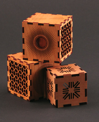
 
Once I started looking at this I realised there was a better way to create a mock-up front-panel.

Frikkin' lasers


A wooden front-panel


Here in the UK I found Razorlab. Their prices are reasonable so I took a design I'd already created in Front Panel Designer saved it as vector file (.svg) and then imported that to Inkscape. The design is placed in a special template provided by Razorlab which matches the size of the material. The way it works is that lines drawn in different colours either cut or line engrave or raster engrave with different strengths.

I quickly did this and sent off my design. A bit too quickly as I'd made a couple of minor mistakes, but nothing too critical. Razorlab state they will deliver in 28-days. Well, mine took over that, by a few days, but a few weekends ago I finally got the panel back.


 The first issue was that one of the holes was not completely cut.


Incomplete cut on the bottom-left


 In fact, that cut wasn't needed. The Cello Volume control should have gone there, but it's also part of the sub-panel on the row of knobs above. I had included a hole for it there and on the next picture you can see the reverse side and where that ended up.

Reverse side

As this is a mock-up it doesn't matter too much about one misplaced control, but it's a good reminder that these things should be checked carefully.

Sub or front panel?

. One thing that makes for a tidy finish is a sub panel. Basically the controls are fixed to the sub-panel and then the front-panel is fixed to sub-panel. The front-panel just has holes and no unsightly bolts and fixings.
In the original SS30 the metal sub-panels are screwed into the wood. The switches have spacers between the switch assembly and the wood to ensure that they sit just proud of the panel surfaces. The knobs' sub-panels are simply screwed into the wood and the thickness of the wood is such that when the knobs are fitted onto the pots they sit just above the surface and don't sick out too far.

In the shot above you can see that I've bolted the pots directly onto the panel. The sub-panel is still there behind but it's just held on buy the bots at the front. You can see on the pots that have knobs on they stand too far out.

But for the switches I had to screw them to something and so I decided I might as well make them sit back and be positioned more or less correctly.


Now that's done its time to wire everything up.


Friday, February 06, 2015

TEC’s 25 FAVOURITE VINTAGE SYNTHS

The SS30 appears here in a list of the the top 25 vintage synth.

http://www.electricity-club.co.uk/tecs-25-favourite-vintage-synths/

The Electricity Club is an electro-pop site and features many artists who have used the SS30.

"A site that dares to mention LADY GAGA, LITTLE BOOTS, OMD, NEW ORDER and KRAFTWERK in the same breath? A site that likes to talk about the best of the new sounds that are emerging in an invigorated music scene? A site that prefers not to employ phrases such as “80s”?"


Tuesday, February 03, 2015

Priorities

It looks like my deadline of August 2015 will have to be revised.

Firstly there are some nice things happening in my life which will be taking up a lot of time. 

Secondly I've become involved in making some music for a film project (nothing with a budget, but it will get seen). I don't know if it will come off yet but I never want the SS30-M to get in the way of doing some actual music. And music with a deadline is perfect for me as it will get done. It's a shame I won't be able to use the SS30, but maybe a virtual one could stand in.

Just before Christmas I started work on a temporary front-panel. I'll post more about that later though.

Monday, December 15, 2014

Sound generation - SS30 Lives! Part 2

On Friday night I made some more wiring fixes and played around with the pitch, detune and vibrato controls.


More on the oscillators and pitch control later.

Wednesday, December 10, 2014

Sound generation - SS30 Lives!

Last night I proved that all the key switches on the K boards are working and that G boards are generating tones on all of those notes. In fact I got some sound out of the SS30!

I had to fix one wire on K2 


Then I hooked the scope to the keying circuit of C2, the first note on K1 and the 8L output of G1. 

The voltage on the key circuit rose when I connected it to earth (-7V up to 0V) and then fell back gradually when I disconnected it, showing that the sustain was working well. 

The output from the generator showed something like what I was expecting, although not exactly. It seemed to have a lot more going on that I was led to believe that it would by the circuit diagrams. It looked like a mix of notes.

G1 8U output

I tried the rest of the keys and got the same result. So far so good.

Then I moved to K2 and G2. I got the same result but this time it was unexpected. The G2 8L output should only have C#3 to F#3. On G2 the octaves are divided as part of the keyboard split option. So, keys on the upper half of the octave should not be generating output on the lower half of the generator board. 
 
G2 Outputs

My assumption had been that I would need to check each output from the G boards. This was my thinking because not only do the same key switches drive both the 8' and 16' outputs on each board, but also those outputs then get routed and mixed together in different combinations. Even if I got something audible at the final output for every key there might still be some missing components to the sound. 
I also assumed that because the switching controls, such as keyboard split and the mixing switches were disconnected there wouldn't be any signal making it's way to the output. 

Now that I am seeing what appears to be a mixed signal at every output I needed to check more carefully.

However rather than do that I decided instead to cut to the chase and see if there was any sound coming from the main output. And there was! 

Every key produced a tone and I could play more than one at once (no reason why it shouldn't, but.. y'know, it was nice to confirm). It sounded awful though. Partly because I just grabbed my Korg Monotron and used that as the amplifier. Also, I suspect there is a lot of noise being generated by the number of loose wires and the proximity of the audio output cabling to the power supply. However after looking at the circuit diagrams again I'm convinced that no sound should be reaching the output at all! With no keyboard split switch connected the bottom two G boards outputs should go nowhere and none of the outputs should get through if the mixing switches (Cello 1, Cello 2, Viola, Vioin 1, Violin 2) are disconnected. I can only guess that what I heard was somehow leaking through. All electrical signals create electro-magnetic radiation which can be picked up in wires, so it's possible.  I've seen stranger things happen. 

My next step will be to methodically trace the signals from the G boards through the circuit. Hopefully I will work out where the signal is getting through as expected and is not getting through .  I will also try reconnecting the switches to see if I can get some more consistent behaviour.


Friday, December 05, 2014

Owners Manual and other scans


After finding the Yamaha IC guide on the Internet Archive, mentioned here, I started to think I should share the owners manual and service manual. Actually, I was thinking it would be useful for me to have scans of them anyway. And of course if I was gong to share them they would need to be in pdf format. However, one of the things that irks me about .pdfs is when there are no links or searchable text in them. Most (all) synth manuals I've ever downloaded are just plain scans of the original printed documents and no active content. Fair enough, but I wanted to do better. So, I embarked on the task of creating scans and converting them to .pdf using Acrobat.

There are actually four documents

Owners Manual - User guide, in other words. "STRINGS SS-30 is a keyed instrument to let you enjoy rich tones peculiar to the strings with this instrument."


Service Manual - The circuit and wiring diagrams. This is, obviously, the really useful bit for the project.


Parts List - Including spectacular exploded 3D diagram


 Block Diagram & Overall Circuit Diagram - No scans yet.


 The service manual folder also contains the parts list and the block diagrams, which are printed on either side of a huge poster sized piece of paper.  I've scanned everything apart from that as I was having problems with the scanner I was using and wanted get on with the rest. It will need stitching together.


I made a start on the service manual and I'm about 80% done.


Work in progress

 It's been a huge job to add all the text though and I got tired of it and decided to knock off the owners manual quickly to show some progress.

So, here it is!


In the pdf all of the text is searchable, the contents section contains links to the relevant pages and the 'How To Use SS30' section has links for the numbered references on the diagram.


Wednesday, November 26, 2014

Benge Studios' SS30

From the It's Full Of Stars blog

Ben 'Benge' Edwards seems to write this blog, although he goes by the handle Zagoba for blogging purposes. It's all about his studio and anything that interests him really. The whole darn thing is a dream for anyone who loves synths and recording technology. He's a lucky devil!

http://myblogitsfullofstars.blogspot.co.uk/2012/05/stringy.html?m=1

This is a nice little SS30 demo he put up. 


Tuesday, November 11, 2014

I Dream Of Wires

A great film and well worth watching even if you're determined not to get sucked into that whole different mess of wires.

http://www.idreamofwires.org/


Also a Garry Numan song and a made up (by the NME) band.

Anyway, as I may have pointed out once or twice there are a lot wires in the SS30. A lot.

I've had a couple of sessions since the G boards were brought back to life just rewiring the K boards.

First off, two of the G boards where disconnected from their corresponding K boards.

De-soldering 
Lots of old, seventies solder. 


Finding a good method for stripping wires as thin as these can be a case of trial and error. Luckily I quickly hit upon using these tweezers to just yank the plastic sheath off.

Strip and twist, strip and twist.
Note the wires are tied with fine string dressing.


Ready to solder

And on the other side, another 49 wires from the K boards to the key switches.


The muck was there when we bought it. Also you can see more loose wires to be reconnected. That yellow one should be attached to AT1.


I had cut all the wires from the key switch PCBs on the assumption I wouldn't need them again. It was also to make handling the whole tangle of boards and wires less difficult. Now I decided to reattach them temporarily to make it easier to test things out.


I removed the switches as they were in a bad way.


And the finished job. A keyboard (if your fingers are earthed).

Monday, October 20, 2014

More power?

The MIDI interface needs a power supply between 8 and 35 volts. The supply current needs to be 15 mA for the interface itself plus whatever is drawn by the output loads.

The loads are connected to a common positive supply switched to ground by the darlington pair drivers.

If the driver voltage is 15V I'd need the 24V rated Coto reed relay which has a coil resistance of 2KOhm. That would be a current draw of (15 / 2000) 7.5 mA each. Assuming worst case of all 49 relays being on at once that would be approx 368 mA.

That's worst case but the question is this: Can the existing SS30 PSU be used to power the interface?

The SS30 PSU has a +15V rail (this is all carefully worked out, you understand) which is rated up to 500 mA. 


What's not clear, is how much of that 500mA is used by the SS30. I know that the +15V rail is not used for the K boards (-7V) or the G boards (all voltages are derived form the -26V rail) but it is used on the LF, OR and F boards. If the interface took the best part of 400mA (absolute maximum) is it likely the SS30 is using under 100mA?

I'm going to have to get the whole thing working and then measure the current on that rail before I can decide whether I need another power supply.

Friday, October 17, 2014

G Board Restoration

Here are the SS30's main PCBs.

It's about 50% wires!

G boards on the left, K, boards at the back and the rest in the middle. During the hiatus I'd cut out a piece of MDF to fit everything to.

I'd checked the power was okay so I decided to start with G boards and see if the oscillator and tone generator ICs were all working. It's a good place to start as all the sound originates there so anything else would be hard to test until they were verified. Also a faulty tone generator chip might be difficult to replace. Yamaha said they had spares when I got the service manual from them way back when, but would they still have these chips? I;d need to find out early on.

I took everything out of the case to gain access.
Don't worry, I've got a wiring guide.
I prodded the scope probes around the G2 board, which is the top most of the stack, and straight-away found that there was a problem. Only one of the tone generator chips was outputting anything. The other IC had no input clock. I wasn't surprised, a quick look around the G boards and I could see several wires that had worked loose at some point.

-26V and -9V supply rails broken on G4
 These wires were all easily fixed, although I did have to check a few more than once on the schematic and wiring diagrams. One group of wires in particular seemed to be linked in a circular fashion. I'm not even sure what they do - something to do with suppressing noise I guessed - so I decided to move on and come back to that mystery later.

I checked the traces again and was disappointed to find that there was still no output on the tone generator ICs. Now I was worried. Damaged ICs would slow things down and a potentially be expensive. However, I've spent enough time fixing electronics to know that you need to be careful not to just swap out an expensive IC because it's appears faulty.

By the way, the SH-101 I'm also fixing does seem to have a broken oscillator chip, but I double checked everything around before condemning it. When I get the replacement I'll still be nervous until it's in and working though.

I went all round the circuit and traced the problem back to the oscillator on the G3 board. There are two identical oscillators built from discrete components, one on G3 and one on G4. This is great as I could A/B compare them to see where the problem started. The first problem I had was using my scope! I was comparing two wave forms and getting one at the right the frequency (around 500KHz) and the other was... well it seemed to be beyond the range of the scope! It was already late, so I went to bed.

Spot the mistake? (the chocolate wrapper is not a clue)
The next evening I started again and got the same problem. This time I went through and systematically worked out that the scope was not showing me the right trace if both signals were connected. I'd got the trigger set-up incorrectly. In the picture above you can see that only channel A is being used as a trigger source. The oscillators are not synced so triggering one from the other gives the problem you can see in the photo.
Once I triggered each input off it's own signal I got two comparable traces. The night before I'd quickly ascertained that the signal from the G3 oscillator was DC shifted negatively by several volts. Having excluded any other issues I was sure this was the problem. It's supposed to be between 0 and -15V, so what was causing this anomaly?

G3 Oscillator being negative.


I eventually disconnected a cable - which I'd just reconnected - that feeds the clock from G3 to G4. Now the signal was biased correctly. So, it was something on the G4 board.

There's something
 When I was fixing that cable I'd noticed this capacitor on the underside of the G4 PCB. It was obviously a modification and didn't appear on the schematic. It also wasn't present in the same position on the G3 board (where the G4 clock enters that board). So, I took it off. Now everything worked perfectly. This cap was clearly an afterthought. It was pulling the signal too low and served no apparent purpose. I suspect that once everything is running I may find out what it was for, but that bridge can be crossed if I get to it.

Test Points 1 and 2 (A and B triggering!)
So, I could now see clean, strong signals from both of the first two test points on the schematic, indicating all was well with the oscillators.

The next job would be to reconnect the wires from K1 and K2 to G1 and G2.


Thursday, October 16, 2014

Power-up

It's been an exciting couple of evenings (yes, that's how I roll) as I've had the actual SS30 hardware out and powered up for the first time in years.

I had done some work a few years back that didn't make it on to the blog. I had put the power supply into a temporary enclosure. It's never going to fit in the rack case so one day it'll get it's own, proper enclosure.


The original back-panel (upside down), power switch and lamp

 Which is a re-purposed carry box


Inside you can see everything looking good

  
Note the Japanese characters on the PCB.


 I checked all the rails and was relieved to see them all looking healthy


But what about the synth itself?